Aerodynamic noise reducing thin-skin landing gear structure

Active Publication Date: 2017-12-21
THE BF GOODRICH CO
View PDF0 Cites 4 Cited by
  • Summary
  • Abstract
  • Description
  • Claims
  • Application Information

AI Technical Summary

Benefits of technology

The patent describes a thin-skin support member used in a landing gear assembly for aircraft. The support member has a semi-circular edge and an elongated surface that define a cavity. The cavity can retain electronic or hydraulic components. The support member is made from a variety of materials like aluminum, titanium, or steel. The assembly also includes a primary support arm, linkage, and secondary support arm. A method of making the thin-skin support member is also provided. The technical effects of this invention include improved efficiency, reduced weight, and increased durability of the landing gear assembly.

Problems solved by technology

Additionally, deployed landing gear may increase the noise signature of an aircraft as a result of air rushing past the deployed gear.

Method used


Image

  • Aerodynamic noise reducing thin-skin landing gear structure
  • Aerodynamic noise reducing thin-skin landing gear structure
  • Aerodynamic noise reducing thin-skin landing gear structure

Examples


Embodiment Construction

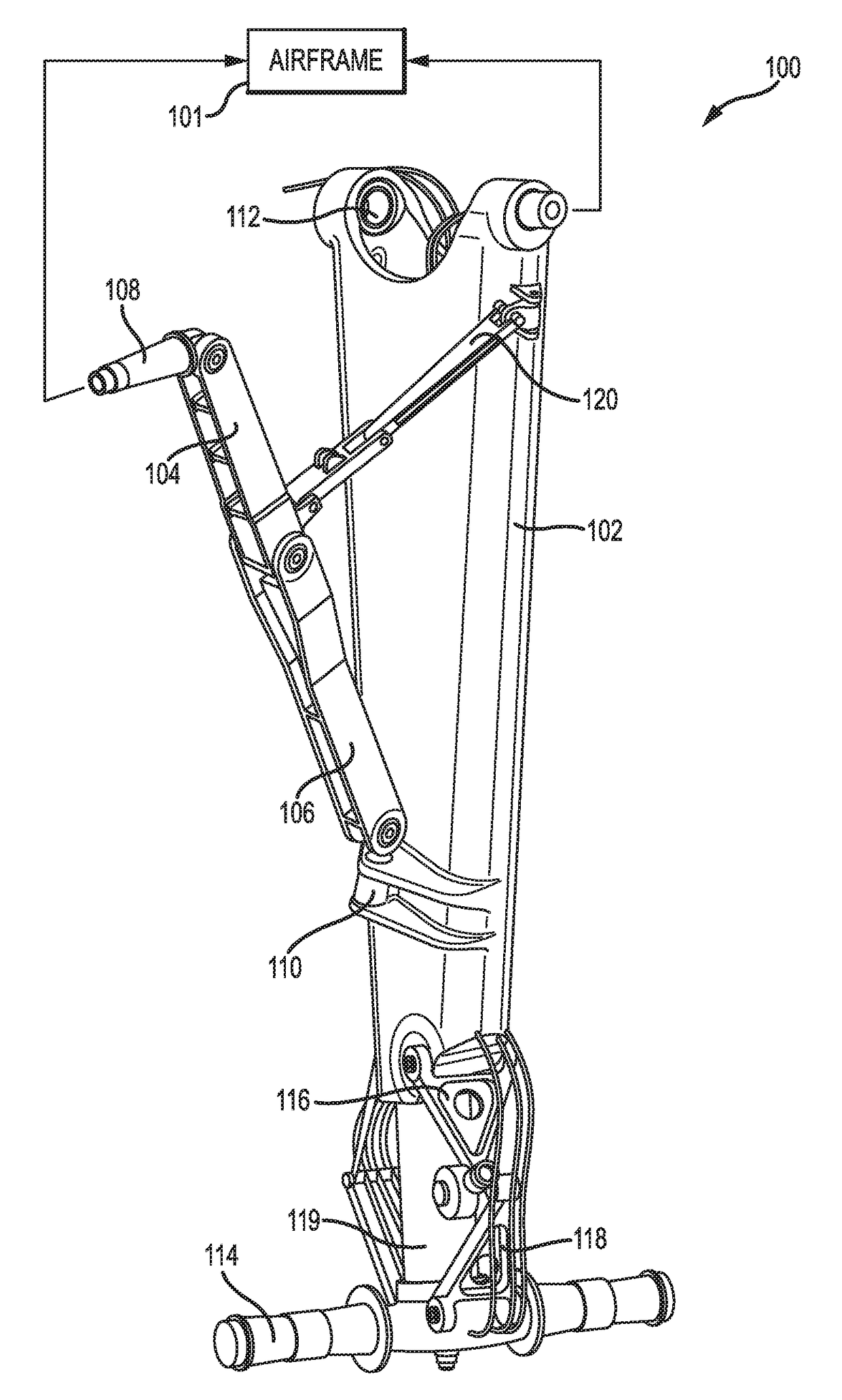
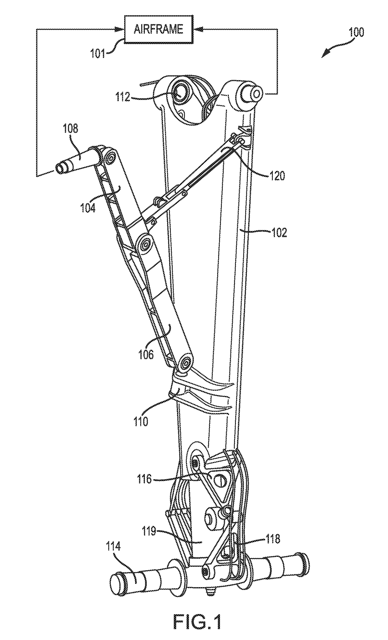
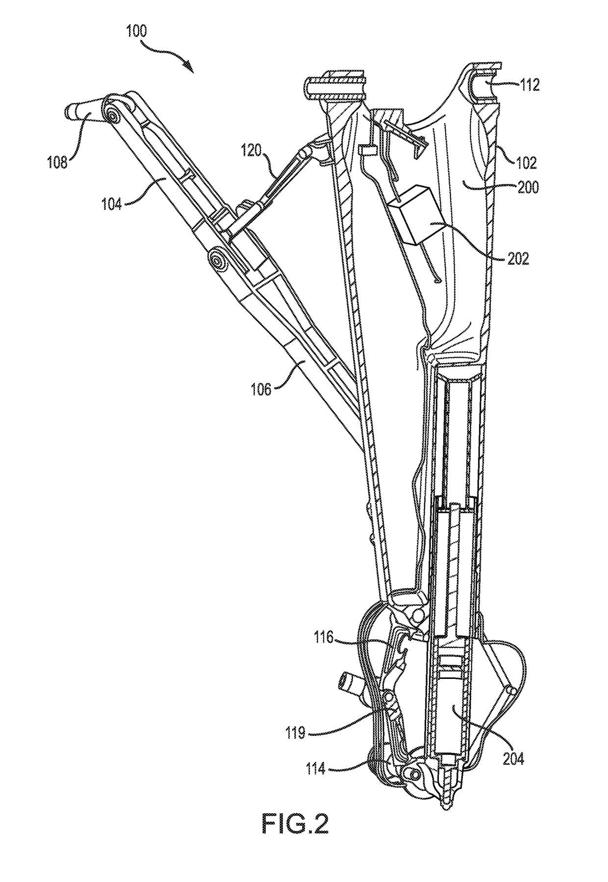
[0020]The detailed description of exemplary embodiments herein makes reference to the accompanying drawings, which show exemplary embodiments by way of illustration and their best mode. While these exemplary embodiments are described in sufficient detail to enable those skilled in the art to practice the disclosures, it should be understood that other embodiments may be realized and that logical, chemical, and mechanical changes may be made without departing from the spirit and scope of the disclosures. Thus, the detailed description herein is presented for purposes of illustration only and not of limitation. For example, the steps recited in any of the method or process descriptions may be executed in any order and are not necessarily limited to the order presented. Furthermore, any reference to singular includes plural embodiments, and any reference to more than one component or step may include a singular embodiment or step. Also, any reference to attached, fixed, connected or th...


PUM


Abstract

A landing gear assembly is also provided. The landing gear assembly may include a thin-skin support member defining a cavity and a cylindrical cavity. A cylinder may extend from the cylindrical cavity with an axle extending from the cylinder. A torsion link may be coupled to the axle and a torsion interface of the thin-skin support member.

Description

FIELD[0001]The disclosure relates generally to aircraft landing gear, with various embodiments relating to thin-skinned landing gear structures.BACKGROUND[0002]Aircraft designers have continuously tried to increase the fuel efficiency of aircraft over the last century. The fuel efficiency of an aircraft may be related to the aircraft's mass and aerodynamic drag. In addition, noise regulations for aircraft at low altitudes encourage reduction of the aircraft's noise signature while it is near the ground. Landing gear can be heavy and aerodynamically resistant. Additionally, deployed landing gear may increase the noise signature of an aircraft as a result of air rushing past the deployed gear.SUMMARY[0003]A thin-skin support member is provided. The thin-skin support member may comprise a semi-circular edge and an elongated surface that define a cavity. A cylindrical cavity may be disposed adjacent the cavity and at least partially defined by the semi-circular edge. The cylindrical cav...

Claims


Application Information

Patent Timeline
IPC IPC(8): B64C25/10B64C25/34
CPCB64C25/34B64C25/10B64C25/02B64C25/60B64C2025/003
Inventor HIMMELMANN, RICHARD A.
Owner THE BF GOODRICH CO
Why Eureka
Try Eureka