Automatic flame extinguisher

a flame extinguisher and automatic technology, applied in the direction of extinguishing devices, combustion regulation, combustion process, etc., can solve problems such as fire burning out, and achieve the effect of preventing burning

Active Publication Date: 2018-02-01
EASY LIFE BRANDS LLC
View PDF13 Cites 3 Cited by
  • Summary
  • Abstract
  • Description
  • Claims
  • Application Information

AI Technical Summary

Benefits of technology

[0006]One embodiment of the automatic flame extinguisher as disclosed herein includes a base for positioning the automatic flame extinguisher in relation to a candle and a lid coupled to the base about a pivot and being selectively positionable between a first open position and a second closed position to extinguish a burning wick of the candle. Moreover, the automatic flame extinguisher may include a timer that includes a clock for selectively activating the pivot to reposition the l...

Problems solved by technology

Once the oxygen content within the interior r...

Method used


Image

  • Automatic flame extinguisher
  • Automatic flame extinguisher
  • Automatic flame extinguisher

Examples


Embodiment Construction

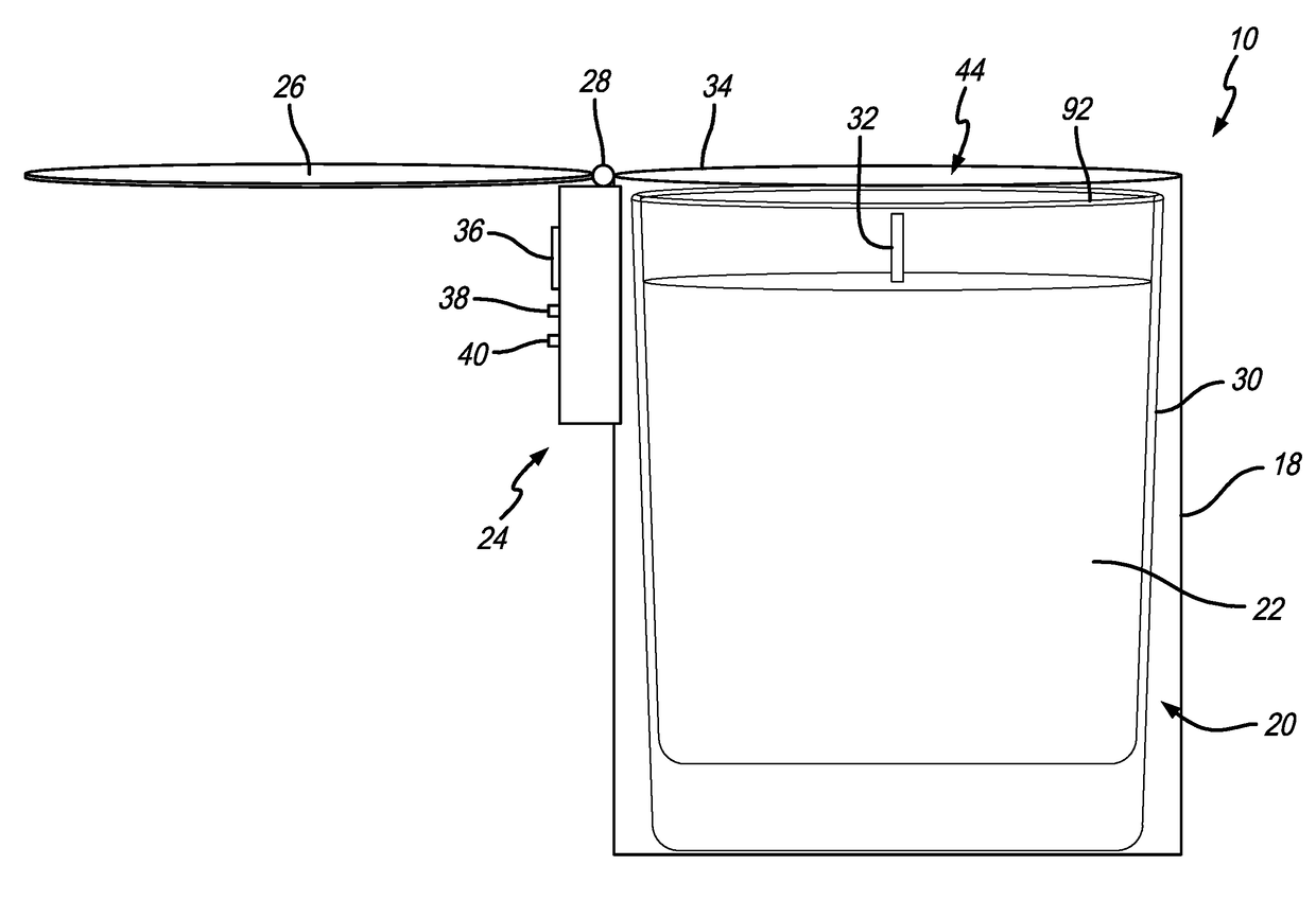
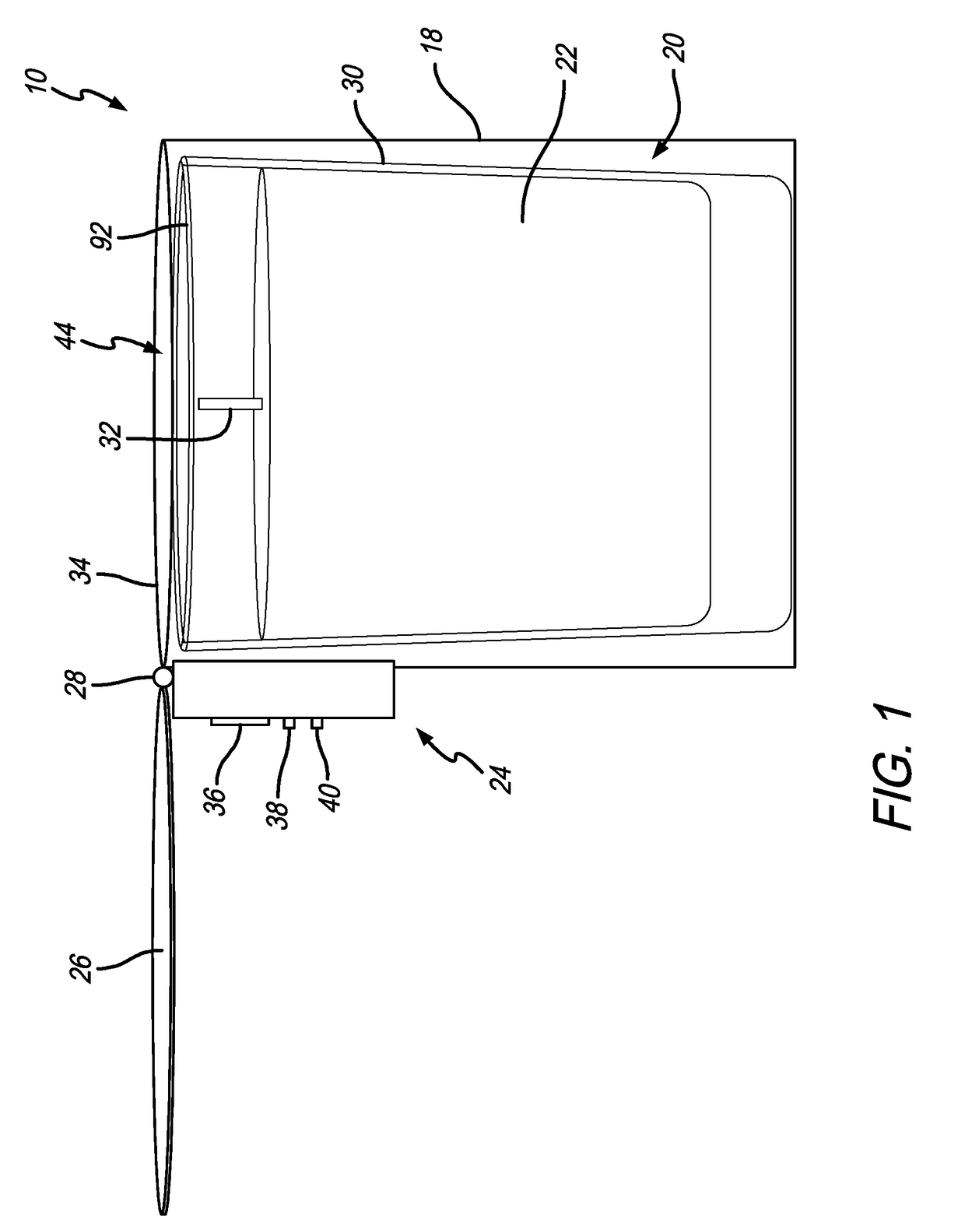
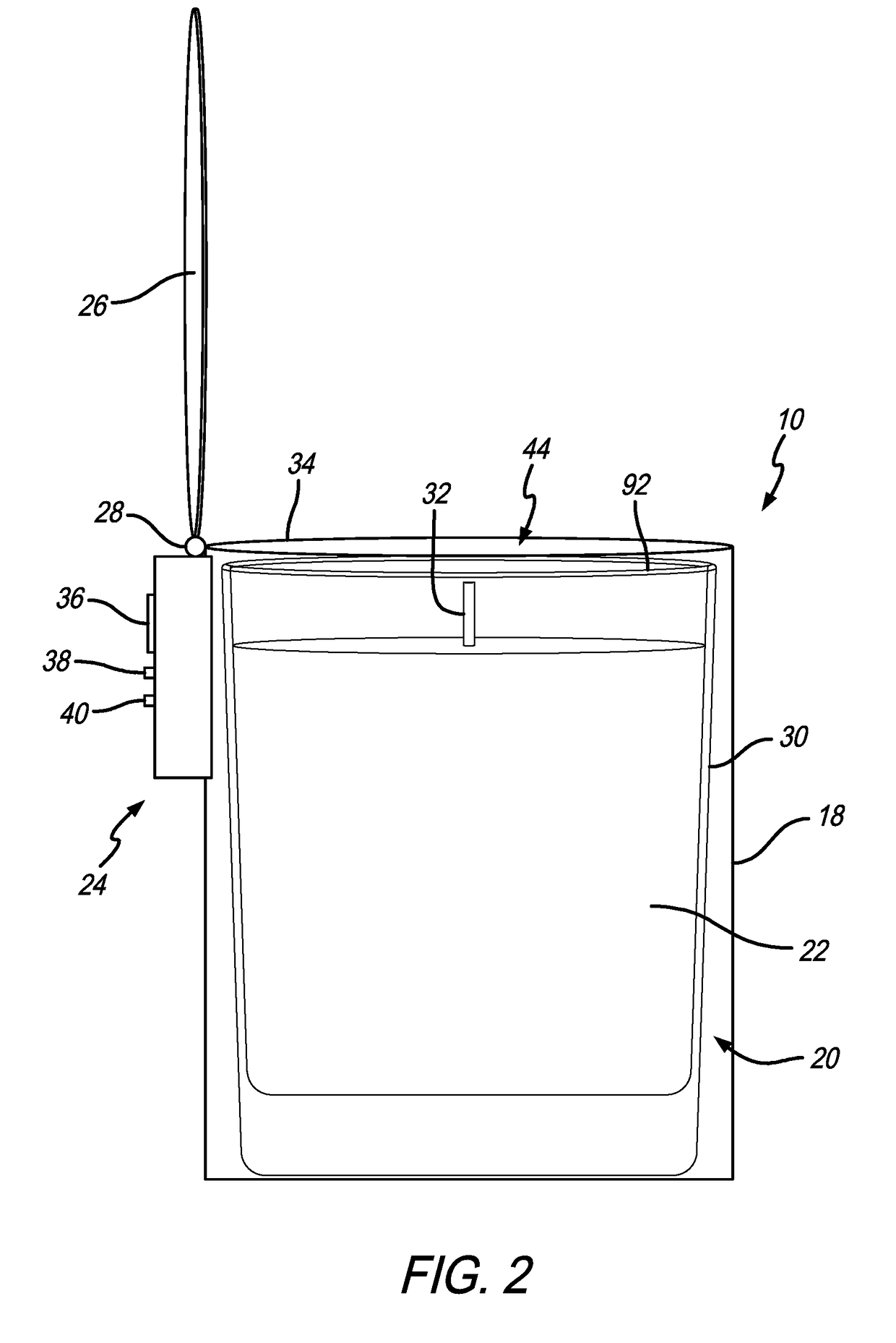
[0042]As shown in the exemplary drawings for purposes of illustration, the present invention for an automatic flame extinguisher is generally referred to by the reference numeral 10 in FIGS. 1-4 and 12-15; as numeral 12 with respect to an adjustable automatic flame extinguisher in FIGS. 6-7; as numeral 14 with respect to a clip-on automatic flame extinguisher in FIGS. 8-9 and 16-17; and as numeral 16 with respect to an annularly-mounted automatic flame extinguisher in FIGS. 10-11 and 18-19. In one embodiment as shown in FIG. 1, the automatic flame extinguisher 10 may include a container-like housing 18 having an internal cavity 20 for holding a candle 22. Furthermore, the automatic flame extinguisher 10 may include a timer 24 coupled to the housing 18 and pivotally coupled to a lid 26 via a revolute joint 28. The housing 18 is illustrated in FIG. 1 as a cylindrical housing, but the housing 18 may alternatively be formed in a variety of other hollow shapes, such as a square, rectangl...


PUM


Abstract

The automatic flame extinguisher may include a base for selectively positioning the automatic flame extinguisher in relation to a candle. A lid coupled to the base may selectively rotate about a pivot between a first open position that allows a burning wick of the candle to receive sufficient ambient oxygen to continue burning and a second closed position to extinguish the burning wick of the candle. In this respect, a timer may include a clock for selectively activating the pivot to reposition the lid from the first open position to the second closed position after the clock reaches a threshold operation time.

Description

BACKGROUND OF THE INVENTION[0001]The present invention generally relates to automatic flame extinguishers. More specifically, the present invention relates to automatic candle flame extinguishers that include a lid automatically pivotable between an open position permitting burning of a candle flame and a closed position whereby the lid seals the candle thereby extinguishing the flame as a result of a lack of oxygen therein.[0002]Candles are widely known in the art and may be formed by enclosing a thread within a wax-based material such as beeswax or paraffin. In this respect, the wax-based material may be formed into various different sizes, shapes, and designs during manufacture. After igniting an exposed end of the thread extending out from the wax-based material (e.g., generally the top), heat from the burning wick may liquefy the wax into a flammable fuel that allows the flame to continue to burn. In respect, candles may be designed to generate various light output, emit variou...

Claims


Application Information

Patent Timeline
IPC IPC(8): F23Q25/00
CPCF23Q25/00F23N5/00F21V35/00F23N5/20
Inventor GAUDIOSO, SHAHESTA
Owner EASY LIFE BRANDS LLC
Why Eureka
Try Eureka