Dental Implant System

a technology of implant system and dental implant, which is applied in the field of dental implants, can solve the problems of reducing the service life of the dental implant,

Active Publication Date: 2018-09-27
BROWN ALAN
View PDF4 Cites 2 Cited by
  • Summary
  • Abstract
  • Description
  • Claims
  • Application Information

AI Technical Summary

Benefits of technology

[0011]In another aspect, the invention is a dental implant system, for implantation into a jawbone of a patient that includes a dental implant fixture. An internal locking collar extends upwardly from the dental implant fixture. The internal locking collar defines a central bore extending downwardly into the dental implant fixture. A first slot locking mechanism canal has a first portion, terminating in an end, that is parallel to the central bore and a second portion that extends transversely from the end of the first portion. An external collar is disposed around the internal locking collar so as to prevent intrusion by surrounding tissue of the patient into the central bore and the first slot locking mechanism canal. An abutment for cement includes a base surface defining a central hole that has a diameter greater than the central bore and includes a prosthesis attachment surface extending upwardly therefrom. A male locking mechanism includes at least one first tab extending outwardly therefrom. The male locking mechanism is configured to be pushed through the central hole and into the central bore so that the at least one first tab slides into the first slot locking mechanism canal. When the at least one first tab reaches the end of the first portion and rotational force is applied to the male locking mechanism, the tab will move into the second portion and lock into place, thereby securing the abutment to the dental implant fixture.

Problems solved by technology

Dentures have the disadvantage of not adequately loading their supporting bone (such as the mandible for lower dentures and the maxilla for upper dentures).
This results in shrinkage of the supporting bone and can further result in related health and aesthetic problems.
Furthermore, osteointegrated implants functionally load the mandibular (or maxillary) bone into which they are implanted, thereby inducing strain in the bone under normal functional loading.
When the implantologist secures the abutment to the implant, these surfaces must be perfectly aligned, otherwise the anti-rotation surfaces can be damaged and the abutment can be allowed to rotate.

Method used


Image

  • Dental Implant System
  • Dental Implant System
  • Dental Implant System

Examples


Embodiment Construction

[0020]A preferred embodiment of the invention is now described in detail. Referring to the drawings, like numbers indicate like parts throughout the views. Unless otherwise specifically indicated in the disclosure that follows, the drawings are not necessarily drawn to scale. As used in the description herein and throughout the claims, the following terms take the meanings explicitly associated herein, unless the context clearly dictates otherwise: the meaning of “a,”“an,” and “the” includes plural reference, the meaning of “in” includes “in” and “on.”

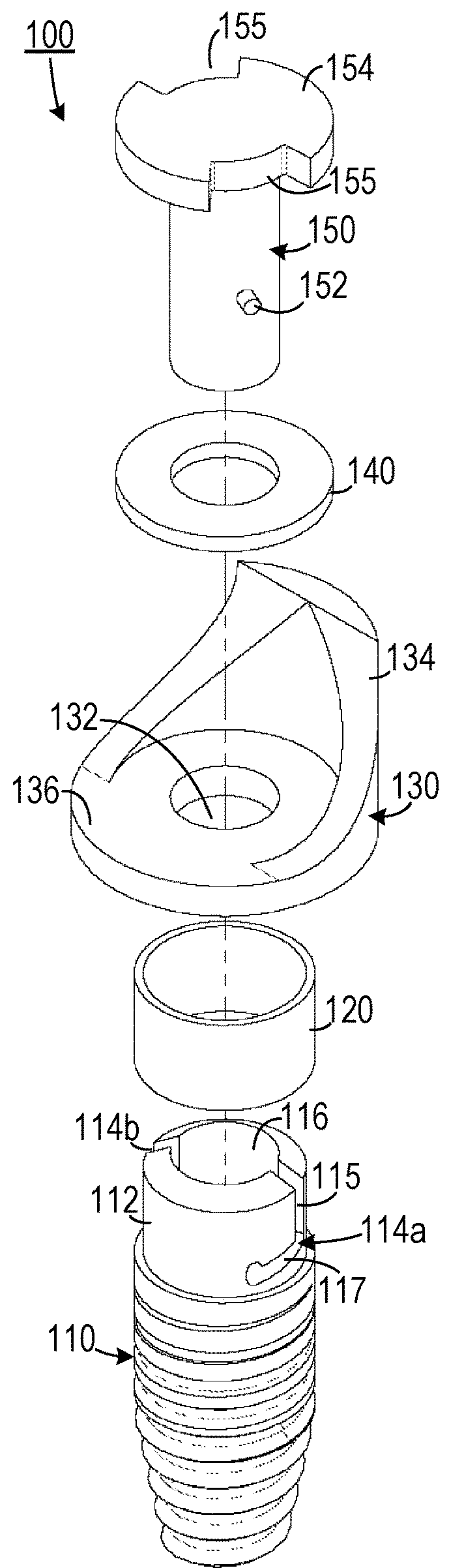
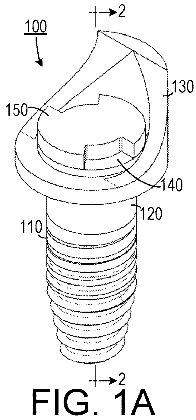
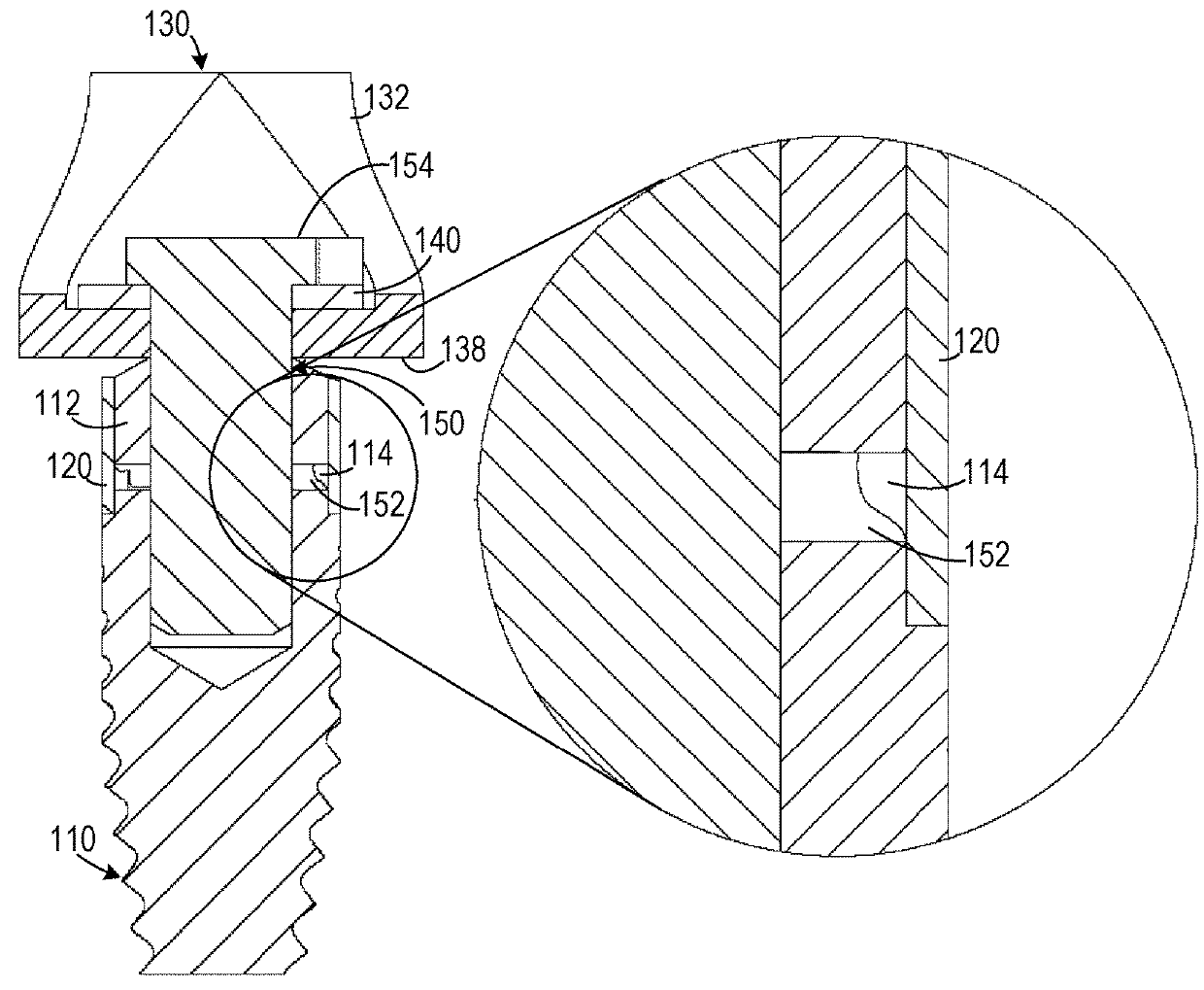
[0021]As shown in FIGS. 1A, 1B and 2, one embodiment of a dental implant system 100 includes a dental implant fixture 110, which could include either a threaded type implant fixture or a cylinder type implant fixture, that is configured to be placed in a prepared cite in a patient's mandibular or maxillary bone. An internal locking collar 112 extends upwardly from the dental implant fixture 110 and defines a central bore 116 extending ...


PUM


Abstract

A dental prosthesis securing system secures a dental prosthesis to a dental implant. An abutment for cement has a base surface for placement against the dental implant. The base surface does not define an engagement shape that requires alignment with a complementary shape defined by the implant. A securing mechanism secures the abutment for cement to the dental implant.

Description

CROSS-REFERENCE TO RELATED APPLICATION(S)[0001]This application claims the benefit of U.S. Provisional Patent Application Ser. No. 62 / 474,711, filed Mar. 22, 2017, the entirety of which is hereby incorporated herein by reference.BACKGROUND OF THE INVENTION1. Field of the Invention[0002]The present invention relates to dental implants and, more specifically, to a dental implant system with a locking abutment.2. Description of the Related Art[0003]Roughly 125 million individuals in the United States alone are missing some of their teeth. One approach to treating patients missing teeth is to supply them with removable dentures. Dentures have the disadvantage of not adequately loading their supporting bone (such as the mandible for lower dentures and the maxilla for upper dentures). An unloaded supporting bone experiences very little strain. When the supporting bone lacks a minimum level of strain, bone resorption occurs. This results in shrinkage of the supporting bone and can further ...

Claims


Application Information

Patent Timeline
Patent Type & Authority Applications(United States)
IPC IPC(8): A61C8/00
CPCA61C8/0068A61C8/0037A61C8/0022A61C8/0056A61C8/0062A61C8/0065
Inventor BROWN, ALAN
Owner BROWN ALAN
Why Eureka
Try Eureka