Unlock instant, AI-driven research and patent intelligence for your innovation.

Electrostatic detection sensor

Active Publication Date: 2018-12-06
PANASONIC INTELLECTUAL PROPERTY MANAGEMENT CO LTD
View PDF0 Cites 1 Cited by
  • Summary
  • Abstract
  • Description
  • Claims
  • Application Information

AI Technical Summary

Benefits of technology

The present invention aims to improve the detection precision of an electrostatic detection sensor, even in a state of being exposed to water. It achieves this by providing a fixing member that can maintain a constant distance between the electrodes on the substrate, even if vibration or thermal shock is applied. This reduces changes in capacitance caused by vibration or thermal shock and improves the detection precision of the electrostatic detection sensor. Overall, the invention provides a reliable and precise solution for detecting finger or similar objects in a water-exposed environment, and also in the case of vibration or thermal shock.

Problems solved by technology

Meanwhile, a door handle of a vehicle is exposed to water during rainfall or vehicle wash.
Therefore, when vibration or thermal shock is applied to the electrostatic detection sensor, the distance between the touch electrode and the touch electrode for difference correction is changed (the positional relation between both touch electrodes is shifted) due to the vibration or the thermal shock, which may deteriorate the detection precision of the electrostatic detection sensor.

Method used


Image

  • Electrostatic detection sensor
  • Electrostatic detection sensor
  • Electrostatic detection sensor

Examples


second exemplary embodiment

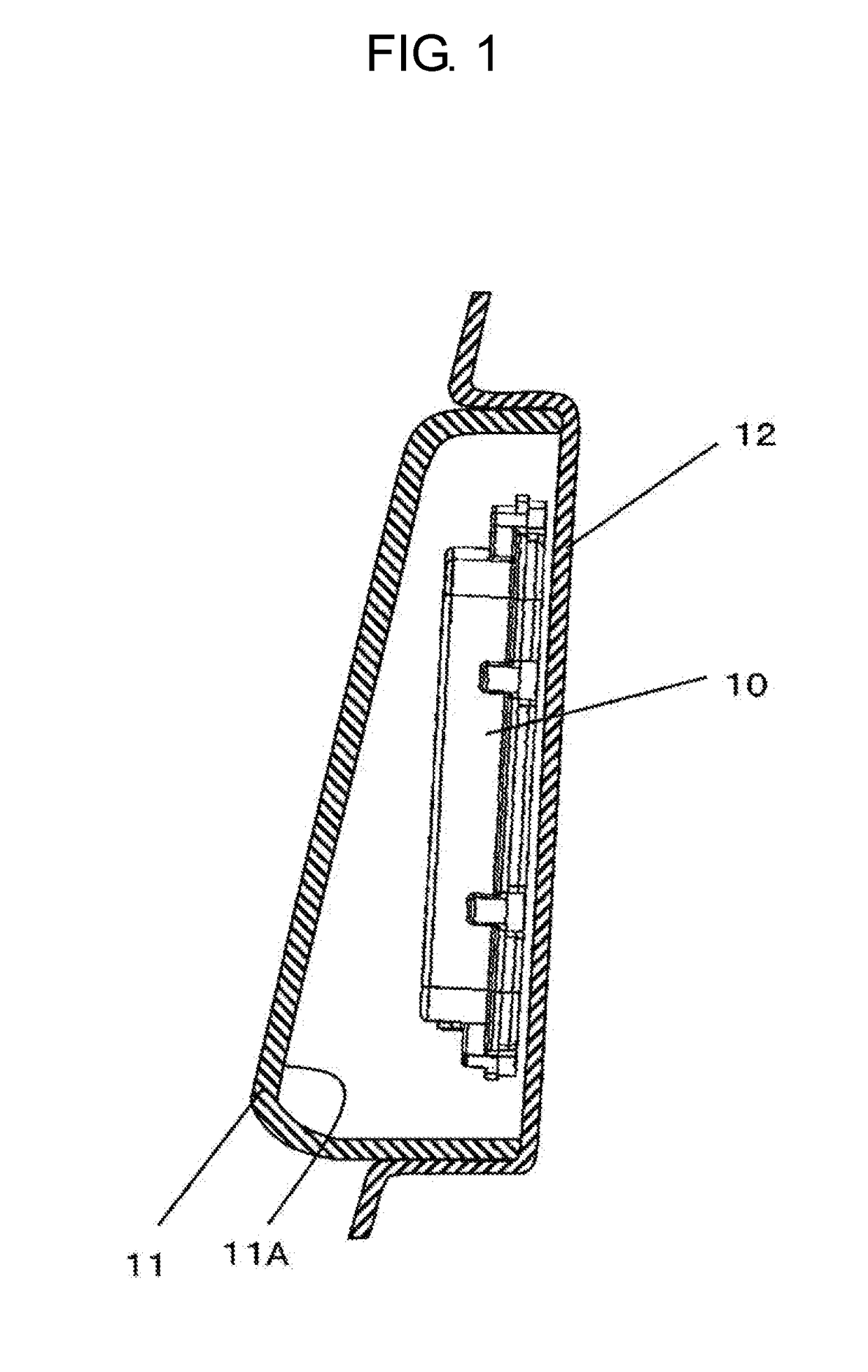
[0068]FIG. 9 is a view illustrating an installation state where electrostatic detection sensor 10 according to the second exemplary embodiment is installed inside resin bumper 11 on a trunk door at the rear part of a vehicle body. Electrostatic detection sensor 10 is mounted on, for example, a recessed surface formed on metal body 12 of the trunk door so as to be recessed toward the front of the vehicle body. The reason why electrostatic detection sensor 10 is installed on metal body 12 is because it is difficult to stably fix electrostatic detection sensor 10 on inner surface 11A of resin bumper 11. When an operator approaches his / her finger or the like toward resin bumper 11, electrostatic detection sensor 10 is sensitive to the approaching finger or the like, and the trunk door is opened.

[0069]FIG. 10 is an exploded perspective view of electrostatic detection sensor 10. FIG. 11 is a sectional view of electrostatic detection sensor 10. Electrostatic detection sensor 10 includes fr...

third exemplary embodiment

[0132]The present exemplary embodiment is different from the second exemplary embodiment in the configuration of electrostatic detection sensor 10, and is the same as the second exemplary embodiment in other points. In the description below, the redundant description of the components same as the components in the second exemplary embodiment may be omitted.

[0133]FIG. 12 is an exploded perspective view illustrating electrostatic detection sensor 10 according to the third exemplary embodiment. FIG. 13 is a sectional view of electrostatic detection sensor 10. Electrostatic detection sensor 10 includes a front case (not illustrated), first electrode 21 to fifth electrode 25, first printed substrate 50 (first substrate), second printed substrate 51 (fourth electrode substrate), third printed substrate 52 (second substrate), fourth printed substrate 53 (second substrate), ground substrate 54 (fifth electrode substrate), holder 55 (fixing member), a back cover (not illustrated), controller...


PUM


Abstract

The electrostatic detection sensor has a first electrode, a second electrode, and a third electrode. A controller connects the first electrode and the second electrode, and applies a first drive voltage thereto to obtain a first intensity. The controller applies a second drive voltage to the first electrode while keeping the second electrode and the third electrode at a ground potential to obtain a second intensity. The controller applies a third drive voltage to the third electrode while grounding the first electrode to the ground potential and keeping the second electrode open to obtain a third intensity. Then, the controller determines whether an object is approaching based on first, second, and third computed values which are computed temporal changes in the first, second, and third intensities, respectively.

Description

TECHNICAL FIELD[0001]The present invention relates to an electrostatic detection sensor mounted to, for example, vehicles or various electronic devices.BACKGROUND ART[0002]Proposals for mounting an electrostatic detection sensor to vehicles or various electronic devices and enabling a predetermined operation based on the detection result of the electrostatic detection sensor have been increasing. PTL 1 discloses a configuration provided with a door handle mounted to be movable relative to a vehicle body of a vehicle, wherein an electrostatic detection sensor is provided inside a housing of the handle.[0003]FIG. 7 is a plan view of the conventional electrostatic detection sensor disclosed in PTL 1. FIG. 8 is a diagram illustrating a detection flow of the electrostatic detection sensor. The electrostatic detection sensor includes rectangular first electrode 1, and second electrode 2 which linearly surrounds the periphery of first electrode 1 with a space therebetween, as illustrated i...

Claims


Application Information

Patent Timeline
IPC IPC(8): H03K17/96
CPCH03K17/962H03K2017/9602G01V3/088
Inventor SAWADA, TAKATERUYAMASHITABESSHI, TAKUMA
Owner PANASONIC INTELLECTUAL PROPERTY MANAGEMENT CO LTD