Device connector

Active Publication Date: 2022-04-28
AUTONETWORKS TECH LTD +2
View PDF0 Cites 0 Cited by
  • Summary
  • Abstract
  • Description
  • Claims
  • Application Information

AI Technical Summary

Benefits of technology

The patent text describes a device connector with an improved shielding performance. The technical effect achieved by this configuration is that the shield current path length is shortest, making the shielding performance better than the case where an L-shaped shield shell is used. The connector is designed to be small and vibration-resistant, with the wire and case-side mounting portions in the same plane. Additionally, a cover made of conductive metal is included, which is connected to the case-side mounting portion and provides further protection against vibration.

Problems solved by technology

Thus, the device connector easily is miniaturized and vibration transmitted from the wire to the housing easily is blocked by the case-side mounting portion.

Method used


Image

  • Device connector
  • Device connector
  • Device connector

Examples


Embodiment Construction

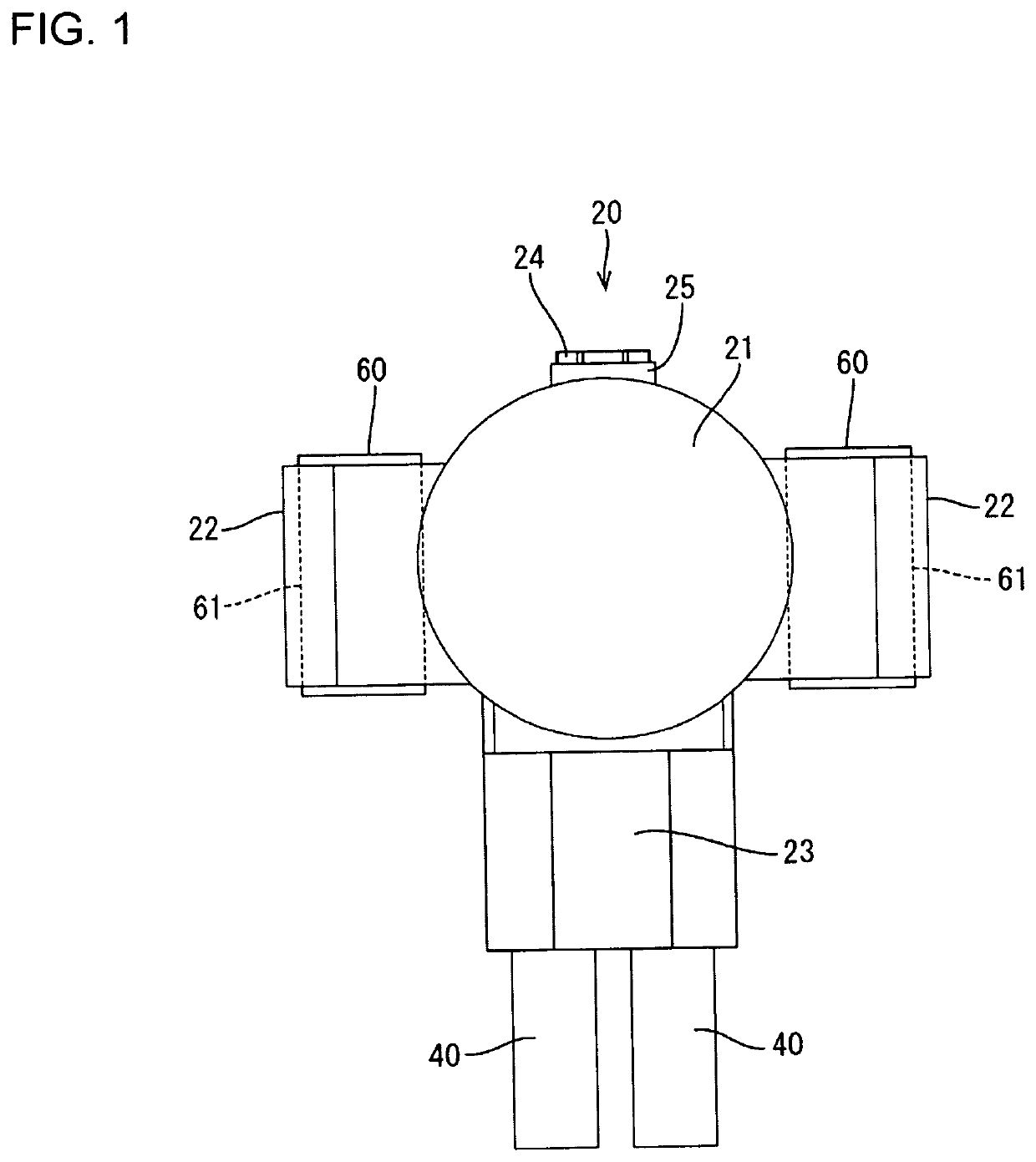
[0022]An embodiment is described with reference to FIGS. 1 to 11. A device connector 10 of this embodiment is a device connector 10 mounted on a case 1 of a device such as an inverter or a motor as shown in FIG. 10. As shown in FIG. 11, the case 1 is provided with a mounting tube 6 having a mounting hole 2 penetrating therethrough. Further, two case-side mounting portions 3 in the form of flat plates project on parts of an outer surface 4 of the case 1 around the mounting hole 2. The case-side mounting portions 3 are coplanar and parallel, and each includes a bolt insertion hole 5 penetrating in a plate thickness direction. Further, as shown in FIG. 9, the case-side mounting portions 3 are perpendicular to the outer surface 4 of the case 1.

[0023]As shown in FIG. 6, the device connector 10 includes a housing 20 fittable into the mounting hole 2 of the mounting tube 6, a conductive cover 30 for covering the housing 20 from behind, wires 40 pulled out in parallel to the outer surface 4...


PUM


Abstract

A device connector 10 disclosed by this specification is a device connector 10 to be mounted on a case 1 of a device and includes a housing 20 fittable into a mounting hole 2 provided in the case 1, a wire 40 pulled out in parallel to an outer surface 4 of the case 1 from the housing 20, a shield member 50 including a wire-side mounting portion 53 and configured to cover the wire 40, and a connecting member (insert nut 60) configured to coaxially arrange and directly connect a case-side mounting portion 3 projecting in a direction intersecting a pull-out direction of the wire 40 from the outer surface 4 of the case 1 and the wire-side mounting portion 53.

Description

BACKGROUNDField of the Invention[0001]This specification relates to a device connector.Related Art[0002]Japanese Unexamined Patent Publication No. 2013-229139 discloses a shield connector to be mounted directly on a device. This shield connector is composed of a male shield connector and a female shield connector. The male shield connector includes a hollow cylindrical male shield shell and the female shield connector includes a vibration reaction-type shield shell. When the male and female shield connectors are connected, the male shield shell and the vibration reaction-type shield shell are connected and shield is dropped from a contact piece of the vibration reaction-type shield shell to a casing.[0003]The above-described shield connector is to be directly mounted on the device, and a connecting direction of the male and female connectors matches a pulled-out direction of shield cables. Thus, the male shield shell and the vibration reaction-type shield shell can be connected dire...

Claims


Application Information

Patent Timeline
IPC IPC(8): H01R13/6593H01R13/74
CPCH01R13/6593H01R13/748H01R13/6596H01R4/32H01R13/648H01R13/6592H01R13/73H01R13/74H01R2201/26
InventorTSUKAMOTO, YUYASAKAGUCHI, KIYOKAZUNISHIO, SHUYA
OwnerAUTONETWORKS TECH LTD