Electrical connector

a technology of electrical connectors and connectors, applied in the direction of relieving the strain of wire connection, correct coupling prevention, coupling device connection, etc., can solve the problems of increasing production costs, not the same, and relatively high moulding cos

Inactive Publication Date: 2000-02-01
SUMITOMO WIRING SYST LTD
View PDF4 Cites 30 Cited by
  • Summary
  • Abstract
  • Description
  • Claims
  • Application Information

AI Technical Summary

Problems solved by technology

However, there is a possibility that the specifications are not the same, depending on whether the ferrite is housed in the male or female connector housing.
In general, the shape of connector housings is complicated due to the f

Method used


Image

  • Electrical connector
  • Electrical connector
  • Electrical connector

Examples


Embodiment Construction

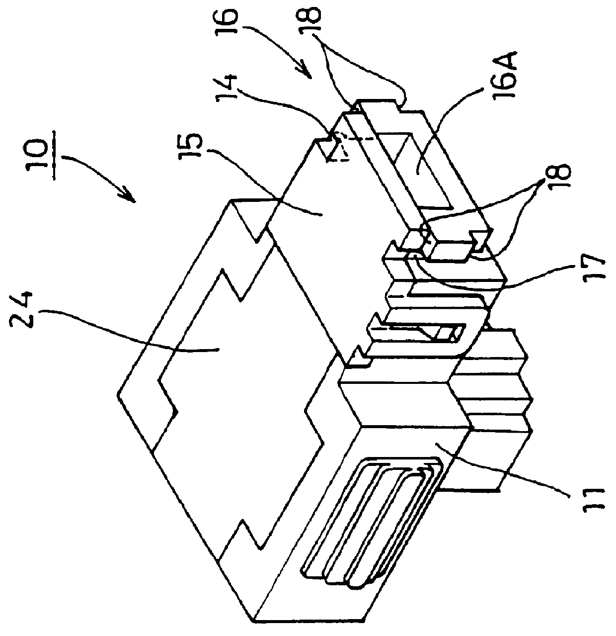
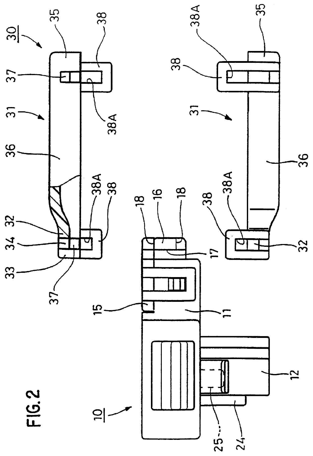
The housing 10 comprises a housing main body 11, a female terminal fitting 20, a retainer 26, a short-circuit cancelling member 24 and a fitting detecting member 25. A fitting member 12 protrudes downwards from the housing main body 11 and fits within a hood of a corresponding connector housing (not shown). A terminal housing chamber 13 which houses the female terminal fitting 20 is formed within the housing main body 11, this terminal housing chamber 13 comprising an upper space 13A which is open on its upper face, and a lower space 13B which joins at a right angle with the fitting member 12 from the anterior edge of the upper space 13A.

The female terminal fitting 20 is L-shaped and comprises a box-like terminal connecting member 21 which connects with male tabs (not shown) of the corresponding connector housing, and an electric wire connecting member 22 which crimps an electric wire 23. The terminal connecting member 21 is housed within the lower space 13B and the electric wire co...


PUM


Abstract

An electrical connector can be fitted with either an electric wire cover (40) or a component installation cover (30), the choice of cover corresponding to the presence or absence of an electrical component (39) in the corresponding connector housing. The electric wire cover (40) or the component installation cover (30) are installed detachably and, as a result, the relatively expensive connector housing (10) is provided with shared components which can be adapted to the intended use.

Description

The present invention relates to an electrical connector.BACKGROUND TO THE INVENTIONAn air bag circuit of an automobile contains male and female connector housings which mutually fit together, either one of the male or female of these connector housings containing ferrite for the purpose of noise reduction. In the usual case, the fitting portions of the male and female connectors have the same specification. However, there is a possibility that the specifications are not the same, depending on whether the ferrite is housed in the male or female connector housing. In these circumstances, when the male connector and the female connector, having differing production patterns, are fitted together, two types of connector housings are produced, those which are able to contain ferrite and those which are not, in order to correspond to the presence or absence of ferrite in the corresponding connector housing. By this means one can avoid the waste of having ferrite within both the male and f...

Claims


Application Information

Patent Timeline
IPC IPC(8): H01R13/719H01R13/703H01R13/641H01R13/64H01R13/70H01R13/56H01R13/7197
CPCH01R13/7197H01R13/641H01R13/7032
Inventor SAKA, YUKINORICHISHIMA, MASAMITSUSEKO, SATOMI
Owner SUMITOMO WIRING SYST LTD
Why Eureka
Try Eureka