Multiple candle lantern

a multi-functional, candle technology, applied in the direction of capillary burners, combustion types, lighting and heating apparatuses, etc., can solve the problems of reducing the illumination and heat of candles, keeping the wicks of candles, and providing adequate ventilation air, so as to achieve greater illumination

Inactive Publication Date: 2000-02-29
DRAPER GREGORY L
View PDF10 Cites 25 Cited by
  • Summary
  • Abstract
  • Description
  • Claims
  • Application Information

AI Technical Summary

Benefits of technology

to provide an improved candle lantern which uses multiple candles for greater illumination.

Problems solved by technology

One drawback with such candle lanterns is that they produce relatively small amounts of illumination and heat.
One drawback with multiple candle lanterns is securely attaching each candle inside the lantern during use.
Another drawback is keeping the candles' wicks at a constant, optimal position behind the viewing windows as the candles burn.
A third drawback is providing adequate ventilation air to support combustion of multiple candles.

Method used


Image

  • Multiple candle lantern
  • Multiple candle lantern
  • Multiple candle lantern

Examples


Embodiment Construction

)

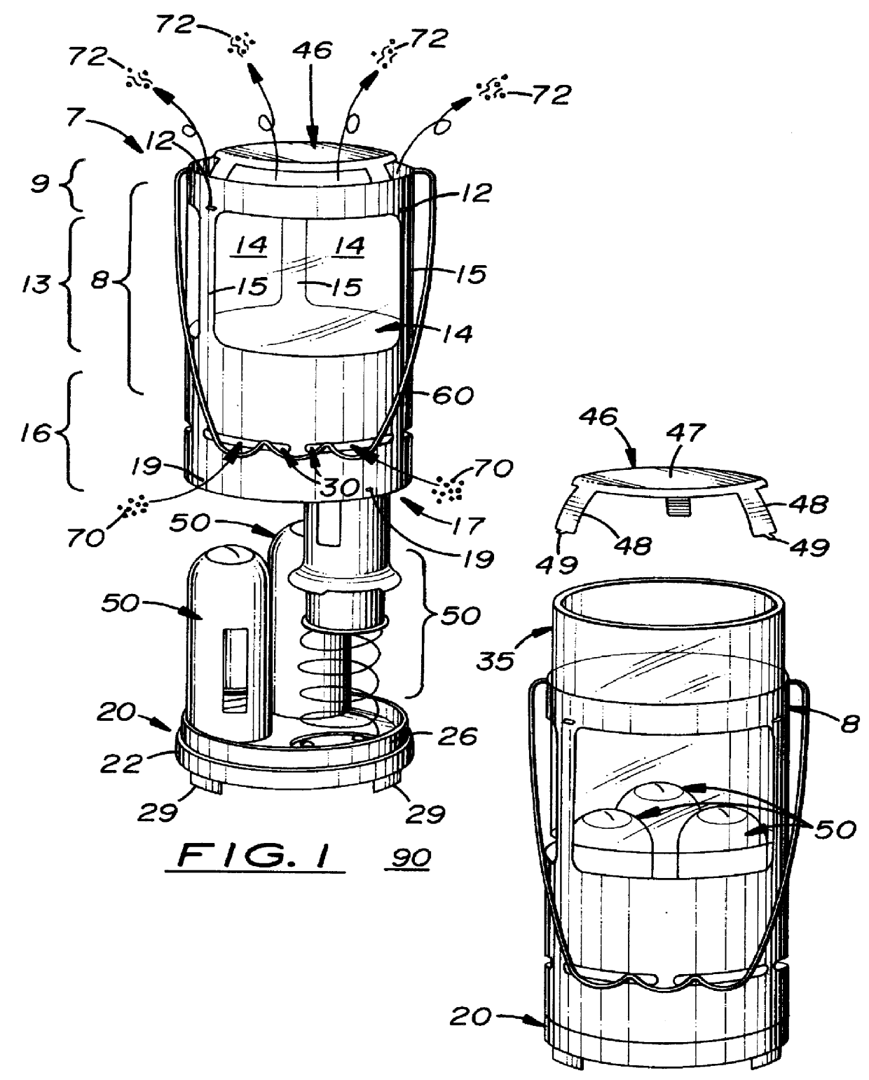
Shown in the accompanying FIGS. 1-5, there is shown a portable candle lantern, generally referred to as 7 designed to be used with a plurality of tube candles 50. The candle lantern 7 includes an upper cover 8 that selectively attaches to a relatively wide, lower base 20 which securely supports the candle lantern 7 in an upright position on a support surface 90.

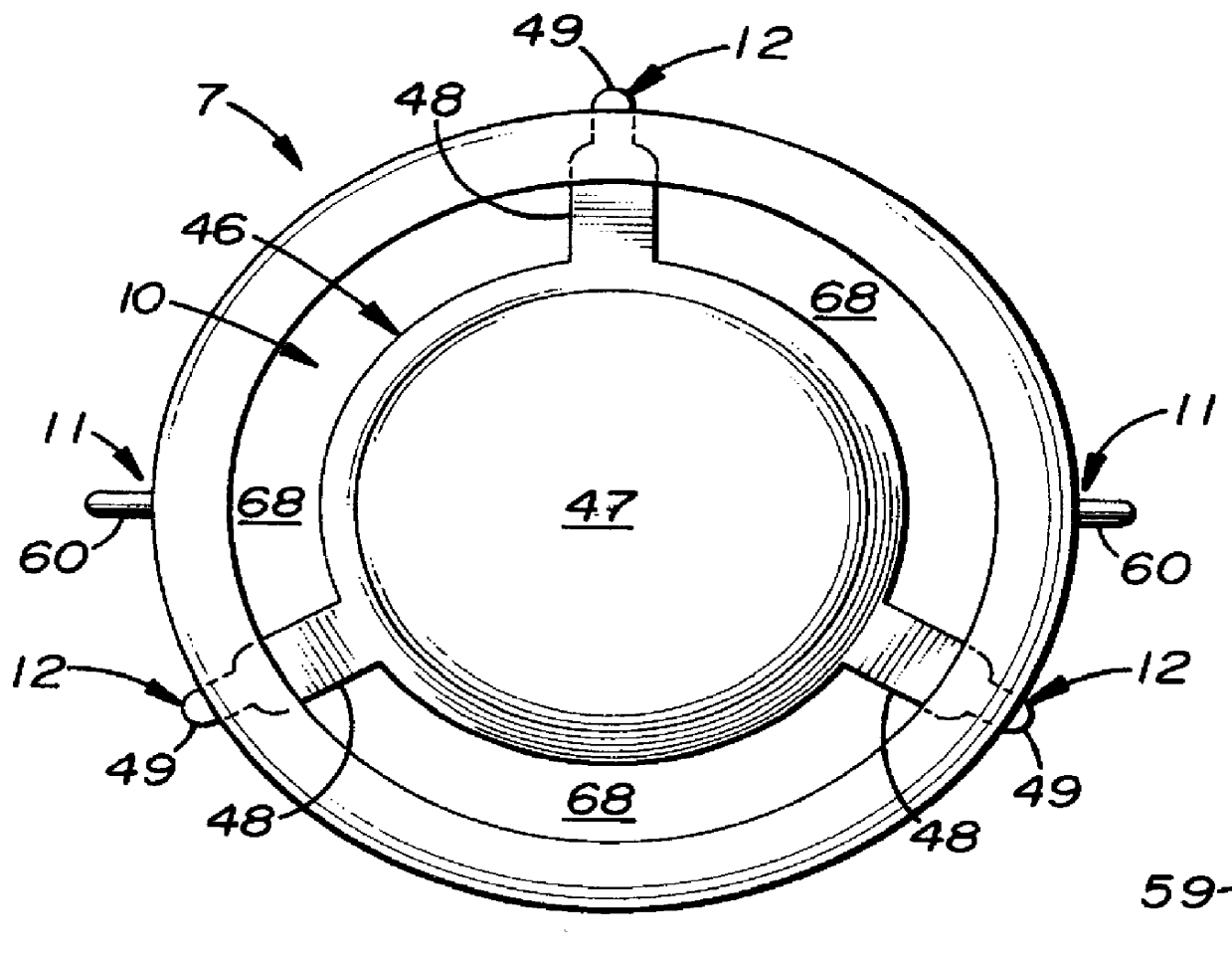
The upper cover 8 is cylindrical with an upper frame section 9, a middle frame section 13, and a lower frame section 16. Located on opposite ends of the upper cover 8 is a top opening 10 and a bottom opening 17. Disposed on the middle frame section 13 are three, radially aligned viewing openings 14 (two are shown) which are separated by three, longitudinally aligned support members 15. A cylindrical glass lens 35 is positioned inside the upper cover 8. Three notches 56 are formed on the sides of the upper cover 8 just below each support member 15 which resiliently traps and holds a glass lens 35 in position inside the upper ...


PUM


Abstract

A multiple candle lantern designed to be used with a plurality of tube candles. The candle lantern includes an upper cover that selectively attaches to a lower base and a heat shield disposed over the top opening of the upper cover. The lower base has a plurality of tube candle recessed spaces formed thereon which hold a tube candle in a longitudinally aligned position thereon. Each tube candle includes a candle longitudinally aligned inside a metal outer tube. A spring is disposed between the lower base and the candle which keeps the candle's wick extending from the upper hole formed on the tube as the candle burns. Formed on the sides of the upper cover near the lower edge are a plurality of air delivery slots which deliver ventilation air directly into the candle lantern and against the sides of the tube candles.

Description

1. Field of the InventionThis invention relates to candle-type illumination devices and, more particularly, to portable candle lanterns.2. Description of the Related ArtTypical portable candle lanterns use one candle housed inside a relatively small, candle holder assembly. Such candle lanterns are described in U.S. Pat. Nos. 5,688,040, 4,566,065, 4,260,365, 4,186,430, and 3,867,625.One drawback with such candle lanterns is that they produce relatively small amounts of illumination and heat. Methods used to increase illumination and heat production include increasing the size of the candle, increasing the total number of candles, and increasing the size of the viewing windows in the candle lantern.One drawback with multiple candle lanterns is securely attaching each candle inside the lantern during use. Another drawback is keeping the candles' wicks at a constant, optimal position behind the viewing windows as the candles burn. A third drawback is providing adequate ventilation air ...

Claims


Application Information

Patent Timeline
Patent Type & Authority Patents(United States)
IPC IPC(8): F21V35/00F21L19/00
CPCF21L19/00F21V35/00
Inventor DRAPER, GREGORY L.
Owner DRAPER GREGORY L
Why Eureka
Try Eureka