Image mixing circuit

Inactive Publication Date: 2000-06-20
PANASONIC CORP
View PDF16 Cites 27 Cited by
  • Summary
  • Abstract
  • Description
  • Claims
  • Application Information

AI Technical Summary

Problems solved by technology

Furthermore, when signal levels are matched by adjusting the gain of image signals generated at different exposure levels as a means of achieving a contin

Method used


Image

  • Image mixing circuit
  • Image mixing circuit
  • Image mixing circuit

Examples


embodiment 1

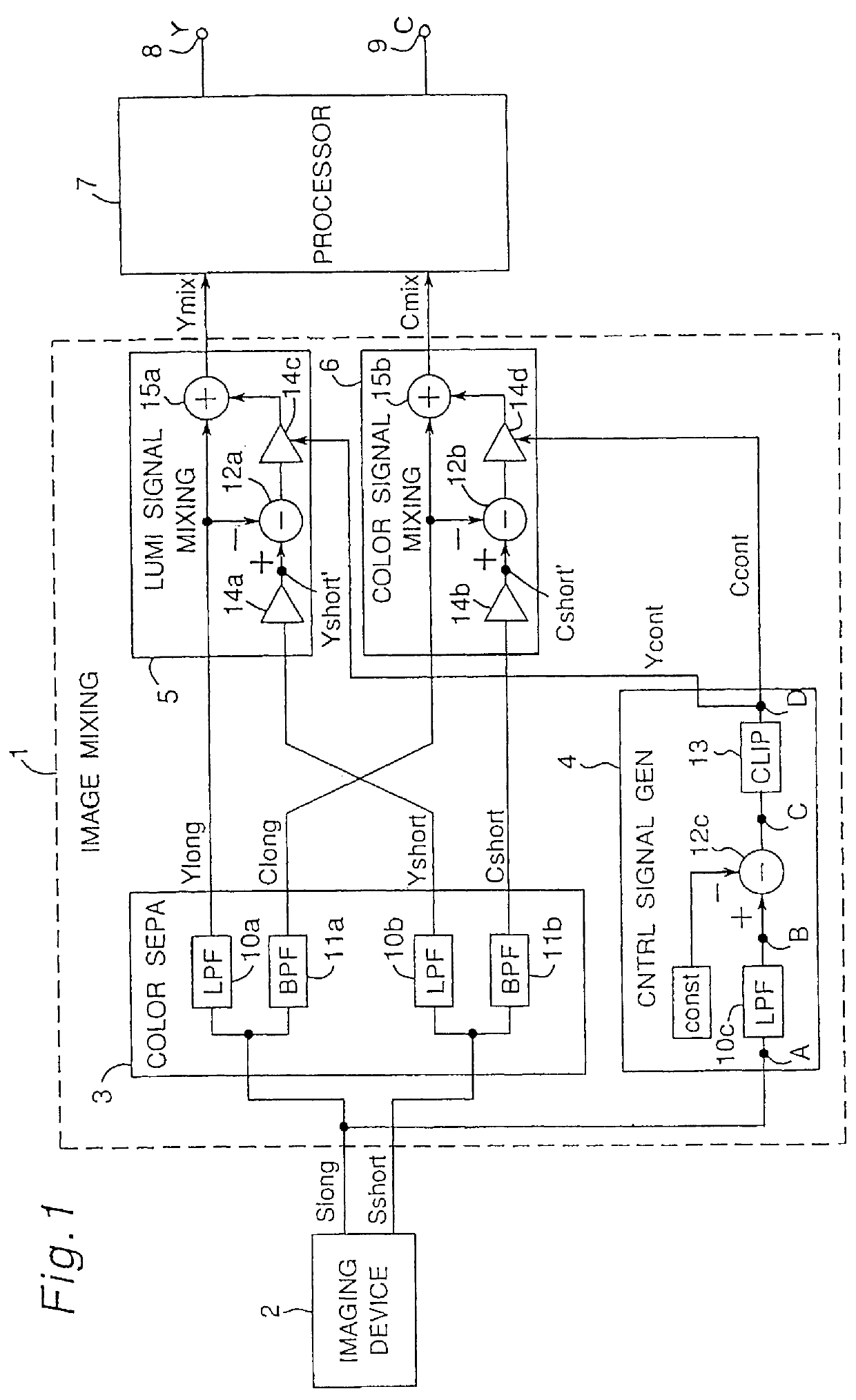
The object of the first embodiment of the present invention is to apply an image signal mixing process suitable for the luminance signal components and color signal components of plural image signals to achieve a continuous gradation characteristic. This is achieved by separating the plural image signals into plural luminance signal components and plural color signal components, generating the control signal needed for image mixing from the plural image signals, and then separately mixing the plural luminance signal components and color signal components according to the control signal.

FIG. 1 is a block diagram of the basic construction of an image mixing circuit according to the first embodiment of the present invention. As shown in FIG. 1, this image mixing circuit 1 comprises an imaging device 2, color separation circuit 3, control signal generation circuit 4, luminance signal mixing circuit 5, color signal mixing circuit 6, signal processor 7, luminance signal output terminal 8,...

embodiment 2

An image mixing circuit according to a second embodiment of the invention is described next below with reference to the accompanying figures.

The object of the second embodiment of the present invention is to apply an image signal mixing process achieving a continuous gradation characteristic in the color signal component even when gradation correction is applied to the luminance signal. This is achieved by normalizing the color signal component based on the luminance signal component in the color separation circuit, and then weighting the color signal component according to the luminance signal after the mixing process of the color signal mixing circuit is completed.

FIG. 5 is a block diagram of an image mixing circuit according to the second embodiment of the present invention. As shown in FIG. 5, this image mixing circuit 1 is essentially the same as that of the first embodiment, but further comprises normalization circuits 21a and 21b, and a gradation correction circuit 22.

Two ima...

embodiment 3

An image mixing circuit according to a third embodiment of the invention is described next below with reference to the accompanying figures.

The object of the third embodiment of the present invention is to apply an image signal mixing process whereby interline differences in the luminance signal level are suppressed, and a continuous gradation characteristic in the color signal component is achieved. This is achieved by the control signal generation circuit generating a color signal using the signal with the highest luminance level selected from the signals with a superposed color signal component in the vicinity of a particular target pixel.

FIG. 7 is a block diagram of the control signal generation-circuit 4 in an image mixing circuit according to the third embodiment of the present invention. As shown in FIG. 7, this control signal generation circuit 4 comprises a delay circuit 31 and a maximum value selector 32.

The construction and operation of the components of the image mixing ...


PUM


Abstract

An image mixing circuit usable in a video camera for mixing images with a continuous gradation characteristic in both the luminance signal and color signal is provided according to the present invention. A color separation circuit separates plural image signals into plural luminance signal components and plural color signal components. A control signal generation circuit then generates the control signal needed for image synthesis from the plural image signals. A luminance signal mixing circuit and a color signal mixing circuit then separately mix the respective luminance signal components and color signal components according to the control signal.

Description

1. Field of the InventionThe present invention relates to an image mixing circuit used in such devices as video cameras.2. Description of the Prior ArtVarious image mixing circuits for obtaining an image signal with a wide dynamic range from image signals obtained at different exposure levels have been proposed. One device typical of such image mixing circuits as proposed in Japan Unexamined Patent Publication (kokai) 63-306779 (corresponding to U.S. Pat. No. 5,162,914 and No. 5,638,118 both issued to Koji Takahashi et al.) is described below with reference to FIGS. 15 and 16.FIG. 15 is a block diagram of the conventional image mixing circuit. As shown in FIG. 15, this image mixing circuit comprises threshold value generators 101a and 101b, comparators 102a and 102b, evaluator 103, and selector 104.The signal levels of image signals Slong and Sshort generated for images obtained with different exposure levels are compared with separate specific threshold values Th1 and Th2. Mixed im...

Claims


Application Information

Patent Timeline
IPC IPC(8): H04N9/76H04N3/15H04N5/235H04N9/04H04N9/07
CPCH04N5/235H04N9/76H04N9/045H04N5/35581H04N23/70H04N25/589
Inventor YAMAMOTO, YASUTOSHIYONEYAMA, MASAYUKINAKAYAMA, MASAAKITOYOMURA, KOICHI
Owner PANASONIC CORP
Why Eureka
Try Eureka