Mounting structure for center rail of slide door

a technology for mounting structures and sliding doors, which is applied in the direction of roofs, doors, wing accessories, etc., can solve the problem of apk rather conspicuous

Inactive Publication Date: 2002-05-21
TOYOTA SHATAI KK
View PDF8 Cites 9 Cited by
  • Summary
  • Abstract
  • Description
  • Claims
  • Application Information

AI Technical Summary

Benefits of technology

The lower rail member may be mounted so as to cover a lower part of the recess located below the lower edge of the elongation of the window glass. If the lower rail member is painted in a color different from that of the vehicle body and the slide door, for example, in the same color as that of a lace arranged along the belt lines of the doors, the lower rail member and the belt lines can constitute a side line having a sense of continuity on the lateral face of the vehicle body. Thus, it is possible to enhance the visual attractiveness of the lateral face of the vehicle body.
The mounting structure of the aforementioned aspect may be constructed as follows. The slide door is provided with a center roller having a horizontal roller and a vertical roller. The upper rail member is composed of a guide having a generally inverse-U-shaped cross-section and guiding rollwise the horizontal roller and a lower end in the shape of a vertical wall extending downwardly of the guide. The lower end is tightly fastened, by means of a plurality of first bolts provided with a predetermined interval formed therebetween, to a generally vertical lateral wall of the recess. The lower rail member is composed of a horizontal flat guide guiding rollwise the vertical roller, an extension extending outwards from an outer edge of the guide to cover a lower wall of the recess, and an upper end in the shape of a vertical wall extending upwards from an inner edge of the guide. The upper end of the lower rail member is superposed on the outside of the lower end of the upper rail member to cover the first bolts provided with a predetermined interval formed therebetween, integrated with the lower end, and tightly fastened, by means of a plurality of second bolts, to the lateral wall of the recess. Thus, the number of bolts that are visible from the gap between the lower edge of the elongation of the window glass and the lower edge of the recess is reduced. This makes it possible to enhance the visual attractiveness of the lateral face of the vehicle.
The lower rail member may be provided at a plurality of positions along the longitudinal direction with protrusions protruding upwards from an upper edge of the upper end, and the upper rail member may be provided with an upper wall and a lower wall abutting on upper ends of the protrusions and a lower face of the guide of the lower rail member respectively and sandwiching them in the vertical direction. Thus, the lower rail member can be vertically positioned with respect to the upper rail member easily and precisely.
The mounting structure of the aforementioned aspect may be constructed as follows. The upper rail member and the lower rail member are respectively provided at their front ends with curvatures curving towards the interior of the vehicle. A notch is formed in the curvature of the lower rail member, and a pin is arranged in a standing manner on the curvature of the upper rail member. The curvature of the lower rail member is positioned by fitting the pin into the notch. Thus, the curvature of the lower rail member can be positioned with respect to the upper rail member and secured thereto easily and precisely.

Problems solved by technology

This causes a problem of making the gap K rather conspicuous.

Method used


Image

  • Mounting structure for center rail of slide door
  • Mounting structure for center rail of slide door
  • Mounting structure for center rail of slide door

Examples


Embodiment Construction

Hereinafter, a preferred embodiment of the invention will be described with reference to the drawings.

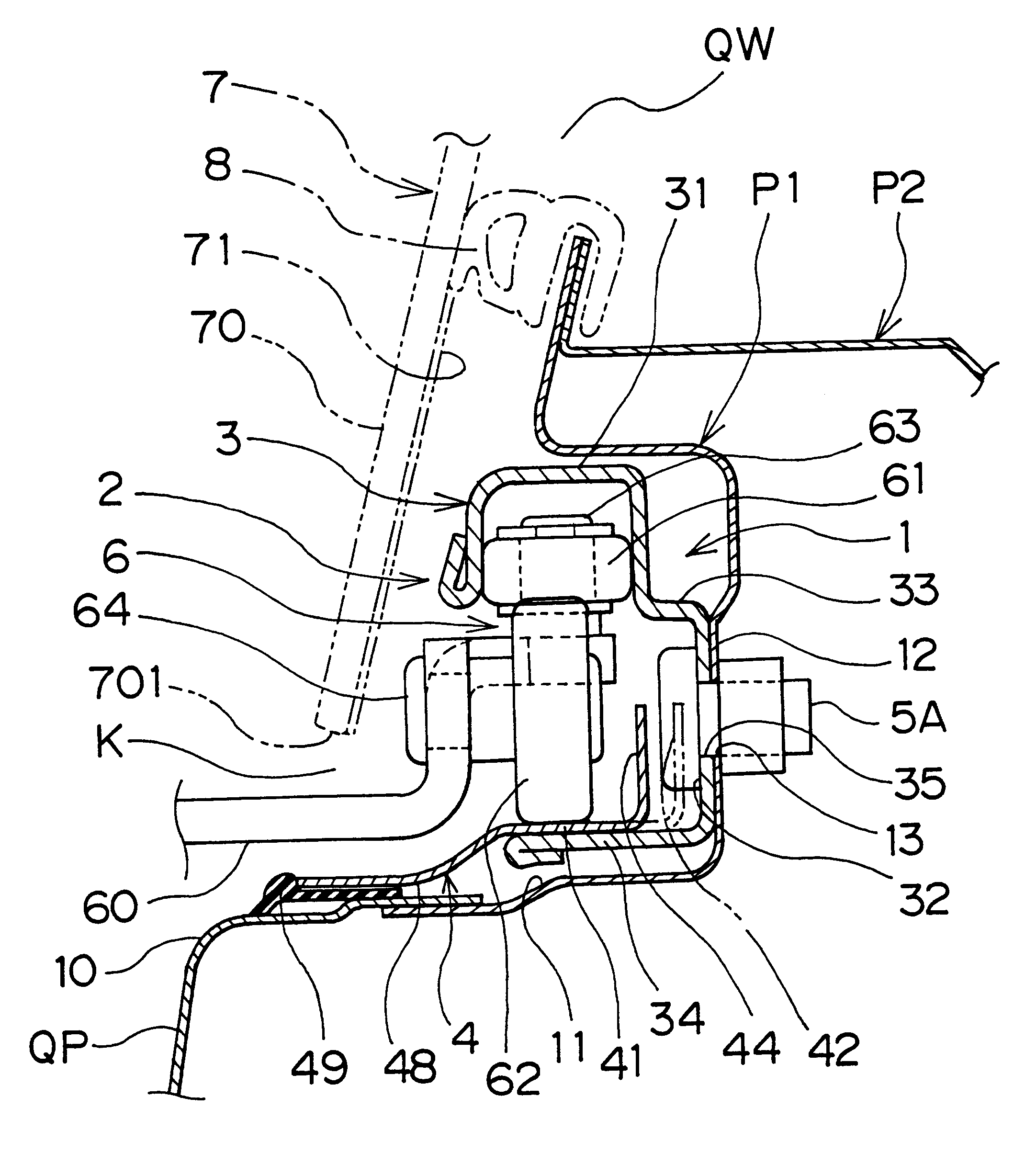
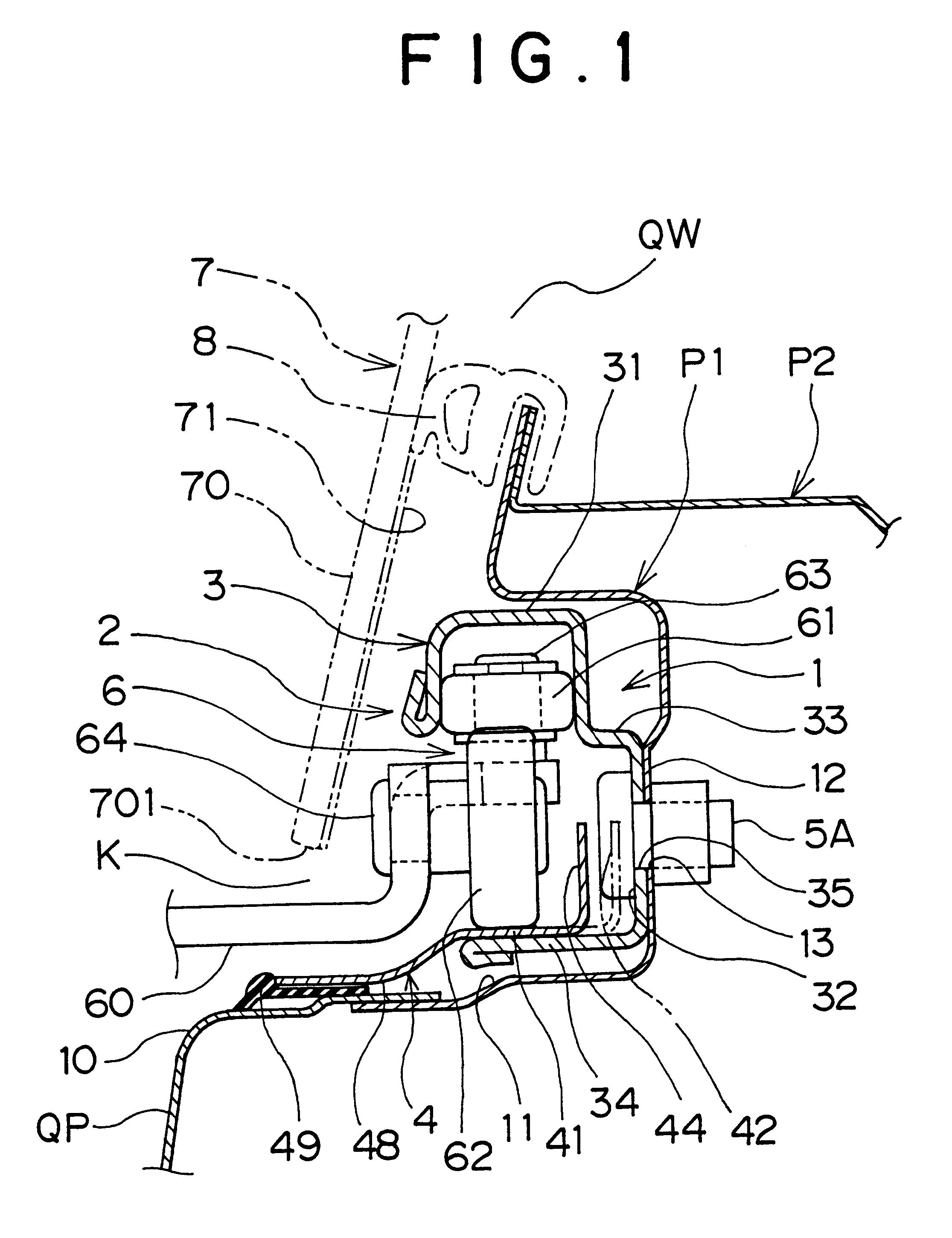
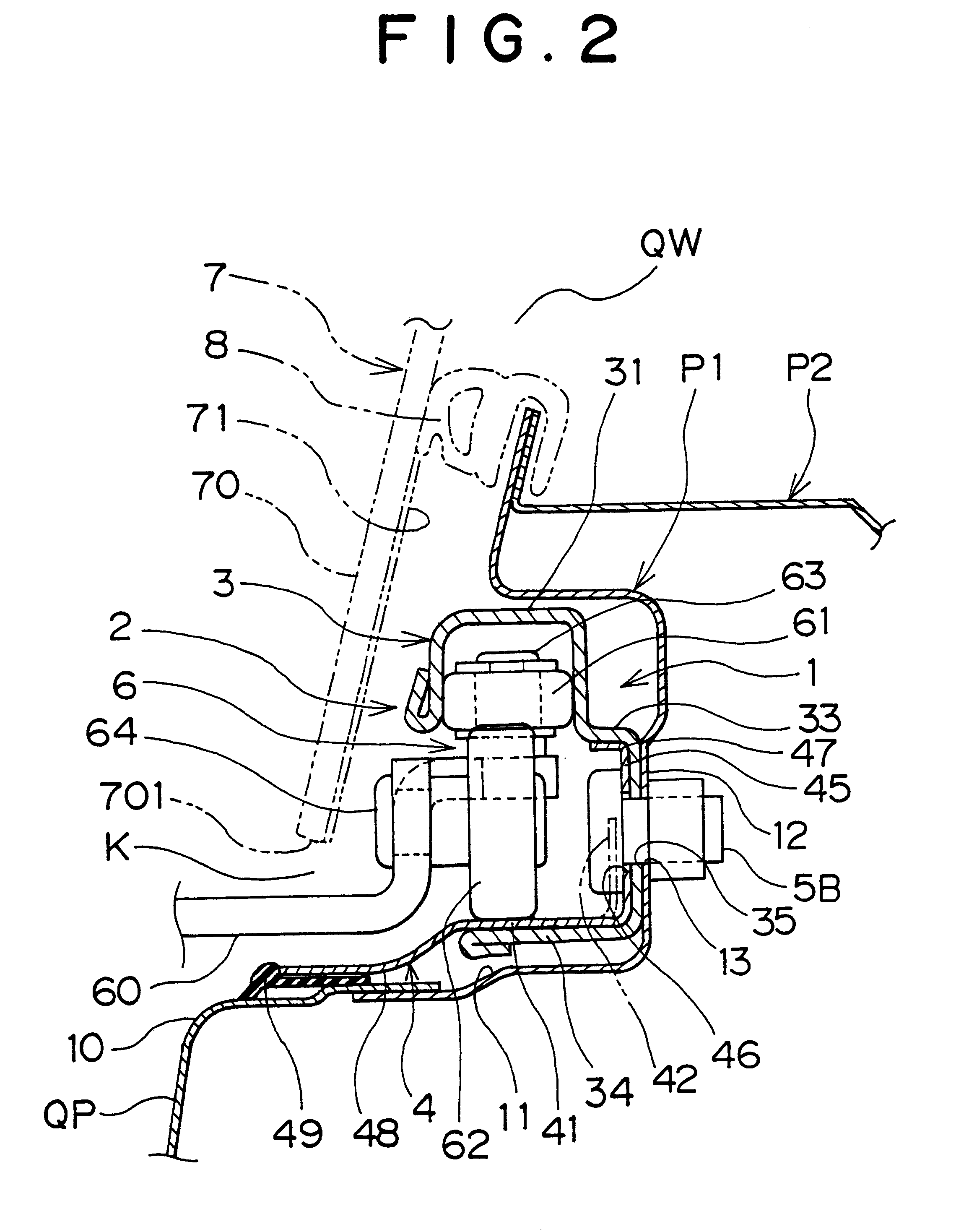
This embodiment is applicable to a lateral part of a vehicle as shown in FIG. 4. That is, a recess 1 is formed in an upper edge of a quarter panel QP along an opening lower edge of a quarter window QW on the lateral face of the vehicle behind a slide door SD, and a center rail 2 is securely fitted to the recess 1. The recess 1 and the center rail 2 are covered with an opaque elongation 70 formed in a lower edge portion of a window glass 7 of the quarter window QW. In the lateral face of the vehicle body, a gap K between a lower edge 701 of the elongation 70 of the window glass 7 and a lower edge 10 of the recess 1 is matched with belt lines B1, B2 of a front door FD and the slide door SD, so that the belt lines B1, B2 and the gap K constitute a side line extending straight and continuously.

As shown in FIGS. 1, 2, the recess 1 is formed in a panel member P1 of a generally U-shaped cr...


PUM


Abstract

In a mounting structure for a center rail, a recess extending horizontally along the lower edge of a window opening of a lateral face of a vehicle body is formed, and the center rail is disposed in the recess to guide a slide door. The center rail is divided in the vertical direction and thus composed of an upper rail member and a lower rail member. The upper rail member is securely fitted to an upper part of the recess and covered with an opaque elongation of the lower edge of a window glass. After mounting the slide door to the lateral face of the vehicle body and painting the vehicle body, the lower rail member painted in a color different from that of the vehicle body is mounted so as to cover a lower part of the recess.

Description

INCORPORATION BY REFERENCEThe disclosure of Japanese Patent Application No. 11-364158 filed on Dec. 22, 1999 including the specification, drawings and abstract is incorporated herein by reference in its entirety.1. Field of the InventionThe invention relates to a mounting structure of a center rail for guiding a slide door on the lateral face of a vehicle body.2. Description of Related ArtJapanese Utility Model Laid-Open No. HEI 6-12976 discloses a mounting structure of a center rail for guiding a slide door as shown in FIGS. 4, 5. In this structure, a recess 1 is formed at the upper edge of a quarter panel QP along the opening lower edge of a quarter window QW on the lateral face of a vehicle body behind a slide door SD, and a center rail 2 is securely fitted into the recess 1. The lower edge of a window glass 7 shielding the opening of the quarter window QW is elongated further downwards than the opening lower edge of the quarter window QW to form an opaque elongation 70. The rece...

Claims


Application Information

Patent Timeline
Patent Type & Authority Patents(United States)
IPC IPC(8): B60J5/06E05D15/06
CPCB60J5/06E05D15/1047E05Y2201/684E05D2015/1057
Inventor TSUBOKURA, ICHIROARAKAWA, SATOSHI
Owner TOYOTA SHATAI KK
Why Eureka
Try Eureka