Vehicular constant-speed control apparatus and method of controlling vehicle speed

a constant-speed control and vehicle technology, applied in the direction of machines/engines, process and machine control, instruments, etc., can solve the problems of engine noise levels deteriorating, engine fuel consumption increasing,

Inactive Publication Date: 2002-12-24
TOYOTA JIDOSHA KK
View PDF4 Cites 10 Cited by
  • Summary
  • Abstract
  • Description
  • Claims
  • Application Information

AI Technical Summary

Benefits of technology

In the vehicular constant-speed control apparatus according to the invention, the transmission is controlled to be downshifted if the operation state detector detects that the internal combustion engine is in an operation state of a fully-closed throttle valve and if the acceleration detected by the acceleration sensor is equal to or greater than a criterion value that decreases as the vehicle speed deviation between the vehicle speed detected by the vehicle speed sensor and the target vehicle speed increases. Thus, in the case where the vehicle speed has increased on a steep downhill, the acceleration of the vehicle is great even if the vehicle speed deviation is small. Therefore, a downshift can be performed quickly. In the case where downshift causes an immediate decrease in vehicle speed while the vehicle runs down a relatively gentle slope, a downshift is not performed until the vehicle speed increases to a measurable value. This eliminates the possibility of an unnecessary downshift being performed to prevent the vehicle speed from increasing. That is, it is possible to downshift the transmission more appropriately, prevent an increase in the vehicle speed deviation between the vehicle speed and the target vehicle speed, and restrain an increase in fuel consumption and deterioration of the engine noise level.

Problems solved by technology

This causes problems of an increase in the amount of fuel consumed by the engine and deterioration of engine noise levels.

Method used


Image

  • Vehicular constant-speed control apparatus and method of controlling vehicle speed
  • Vehicular constant-speed control apparatus and method of controlling vehicle speed
  • Vehicular constant-speed control apparatus and method of controlling vehicle speed

Examples


Embodiment Construction

In the following description and the accompanying drawings, the invention will be described in more detail in terms of a preferred embodiment.

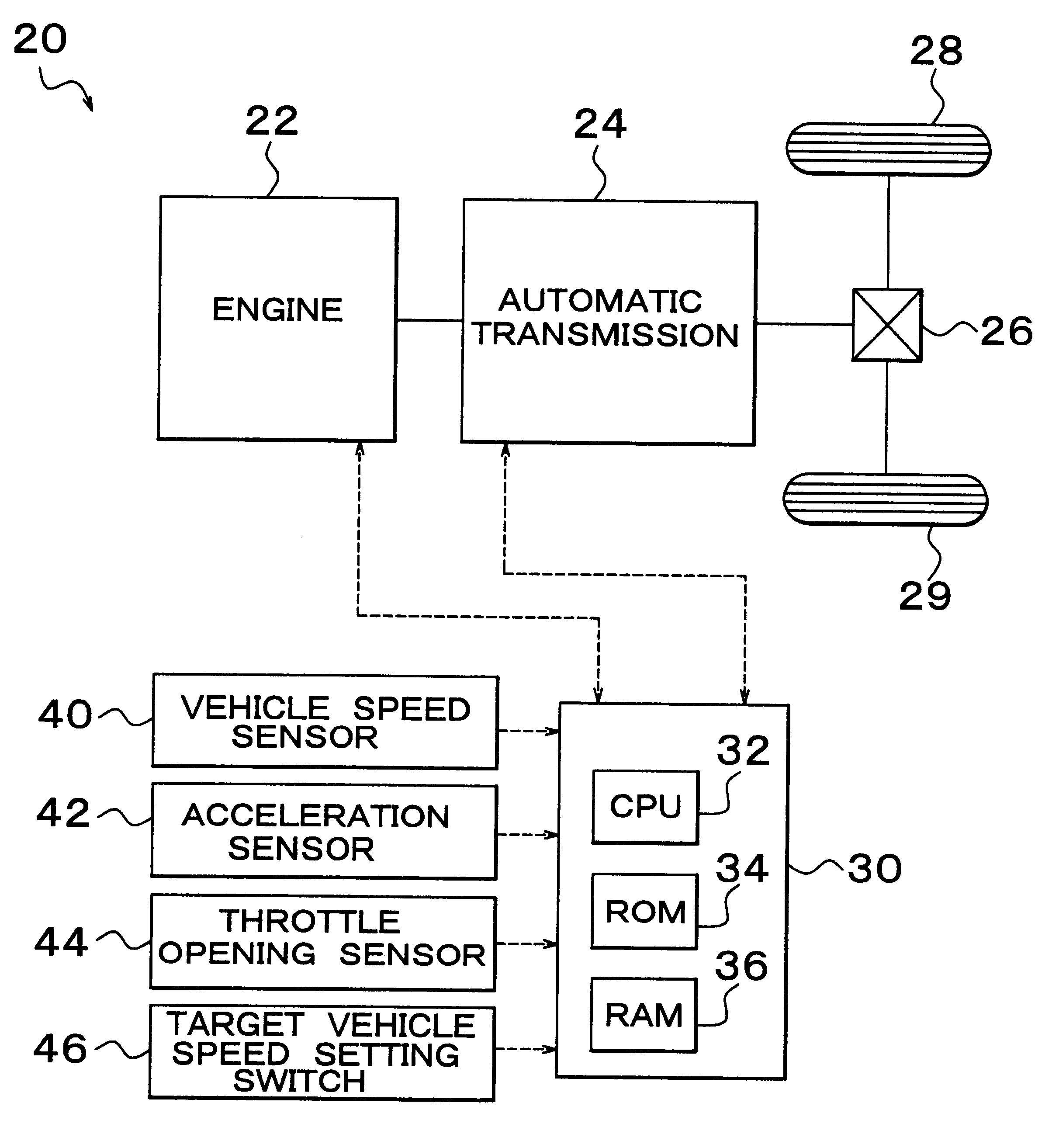
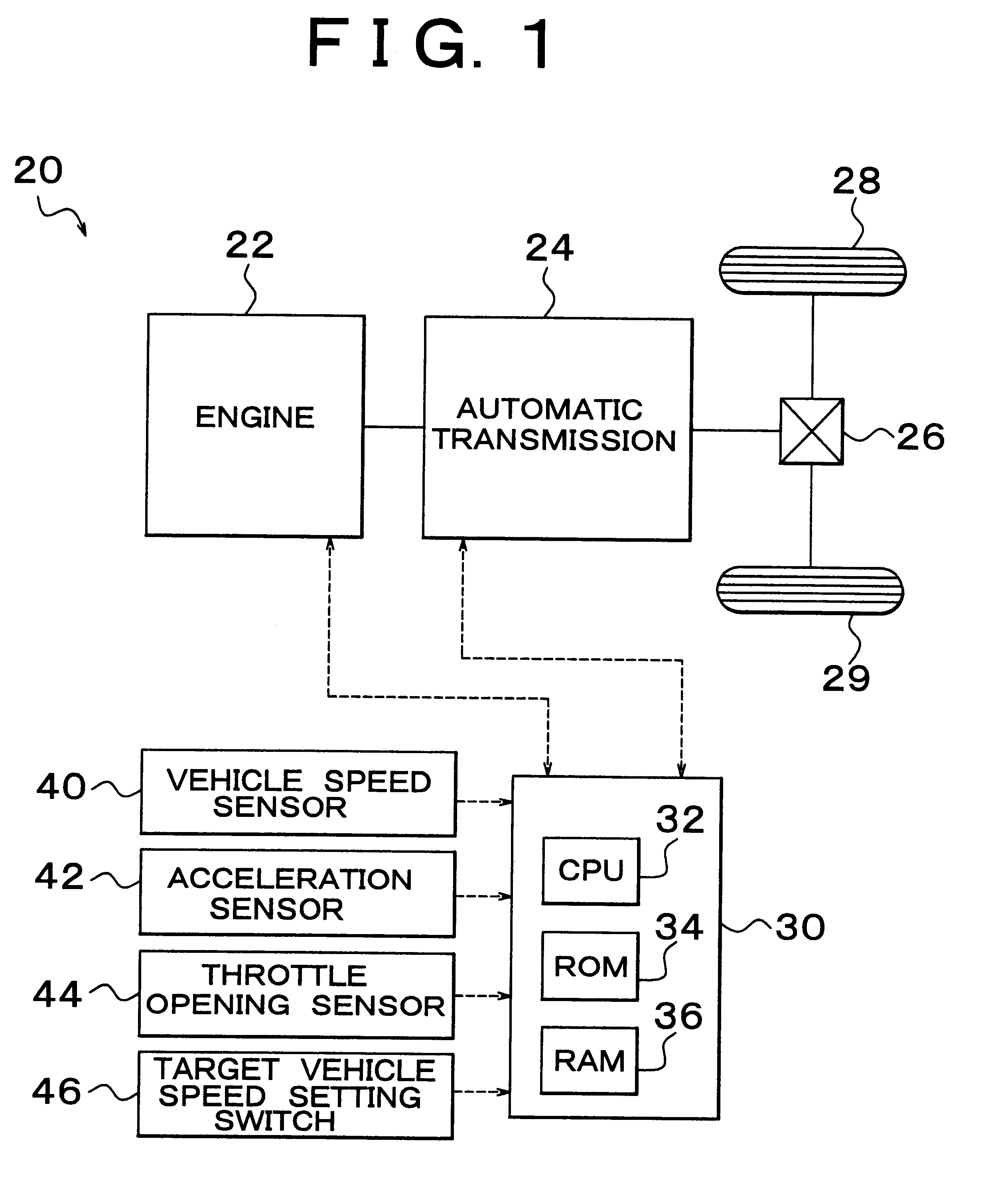
Hereinafter, an embodiment of the invention will be described. FIG. 1 is a block diagram showing an overall construction of a vehicular constant-speed control apparatus 20 according to a first embodiment as an example of the invention. As shown in FIG. 1, the vehicular constant-speed control apparatus 20 is associated with a gasoline engine 22 as an internal combustion engine and an automatic transmission 24 as a transmission that is mechanically connected to a crank shaft of the engine 22 and that can change the rotational speed of the crank shaft in a plurality of stages, and has an electronic control unit 30 that controls the constant-speed control apparatus 20 as a whole.

Although not shown, the engine 22 is fitted with fuel injection valves, a throttle valve for adjusting amount of intake air, and so on. The electronic control unit 30 adju...


PUM


Abstract

If a throttle valve is fully-closed, it is determined whether or not a transmission is to be downshifted, by determining whether or not an acceleration of the vehicle is equal to or greater than a downshift criterion value. The downshift criterion value is set as a value that decreases as the vehicle speed deviation, which is a difference between a vehicle speed and a target vehicle speed, increases. By using a downshift criterion value, an increase in the vehicle speed deviation resulting from a quick downshift on a steep downhill can be restrained. On a gentle downhill, a downshift is not performed even if the vehicle speed deviation assumes a significant value. Thus, it becomes possible to inhibit the vehicle speed from becoming lower than the target vehicle speed during a short period after downshift. Accordingly, an increase in fuel consumption and deterioration of noise of the engine can be restrained.

Description

1. Field of the InventionThe invention relates to a vehicular constant-speed control apparatus and a method of controlling vehicle speed and, more particularly, to a vehicular constant-speed control apparatus that controls operation of an internal combustion engine and gear-shift stages of a transmission such that a vehicle runs at a constant speed, i.e., at a target vehicle speed, and to a method of controlling vehicle speed.2. Description of Related ArtConventionally, as a vehicular constant-speed control apparatus of this type, there has been proposed one which downshifts a transmission if a vehicle speed deviation representative of a difference between a vehicle speed and a target vehicle speed has become equal to or greater than a predetermined value. One such constant-speed control apparatus is disclosed e.g. in Japanese Patent Application Laid-Open No. 7-172209. In this constant-speed control apparatus, a transmission is downshifted while a vehicle runs at a constant speed. T...

Claims


Application Information

Patent Timeline
Patent Type & Authority Patents(United States)
IPC IPC(8): B60K31/02B60K31/04F16H61/16B60K31/00B60W10/04B60W10/10B60W10/11B60W30/00B60W30/14F02D29/00F02D29/02
CPCB60K31/04F16H61/16B60W2510/0604B60W2520/10B60W2520/105Y10T477/69Y10T477/692Y10T477/693Y10T477/676
Inventor TAKAO, SHIRAIMASAMI, NAGASAKA
Owner TOYOTA JIDOSHA KK
Why Eureka
Try Eureka