Wrench

a wrench and wrench technology, applied in the field of wrenches, can solve the problems of two problems encountered in the use of wrenches

Inactive Publication Date: 2004-06-29
LIN CLARE
View PDF0 Cites 17 Cited by
  • Summary
  • Abstract
  • Description
  • Claims
  • Application Information

AI Technical Summary

Benefits of technology

It is another objective of the present invention to provide a wrench that protects a head of a bolt in use.

Problems solved by technology

Two problems are encountered in use of the wrench 10.

Method used


Image

  • Wrench
  • Wrench
  • Wrench

Examples


Embodiment Construction

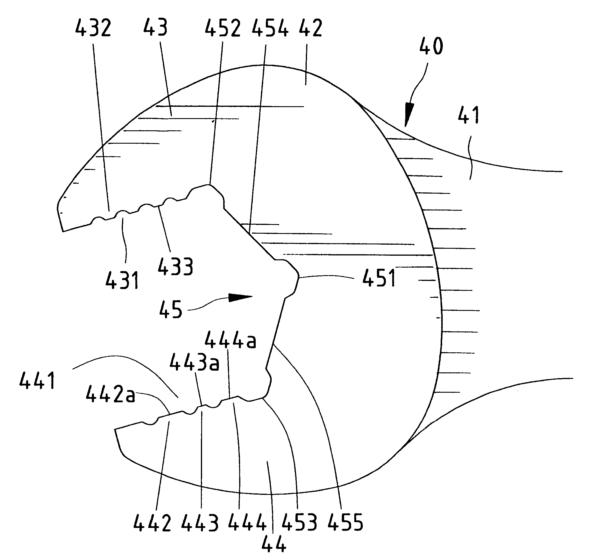
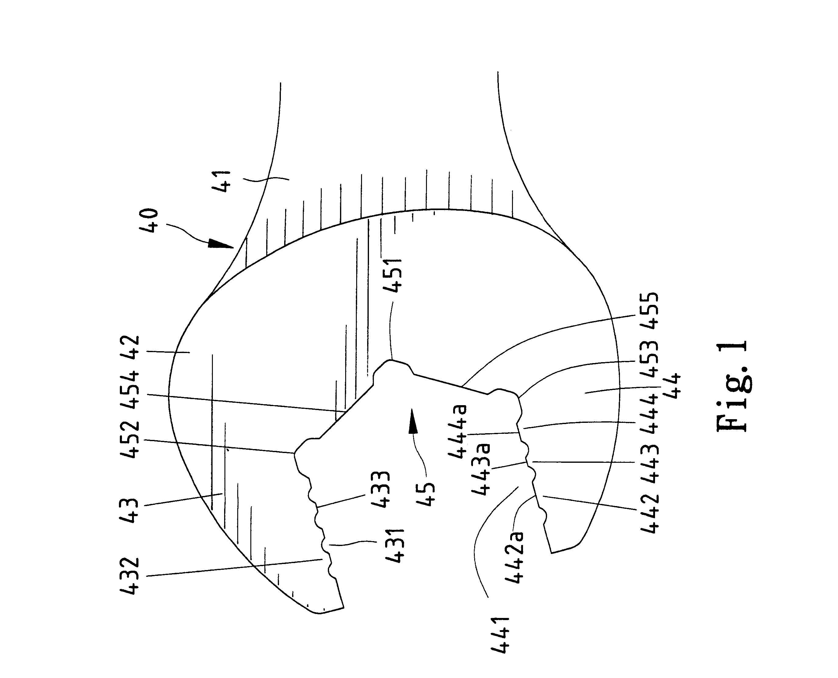
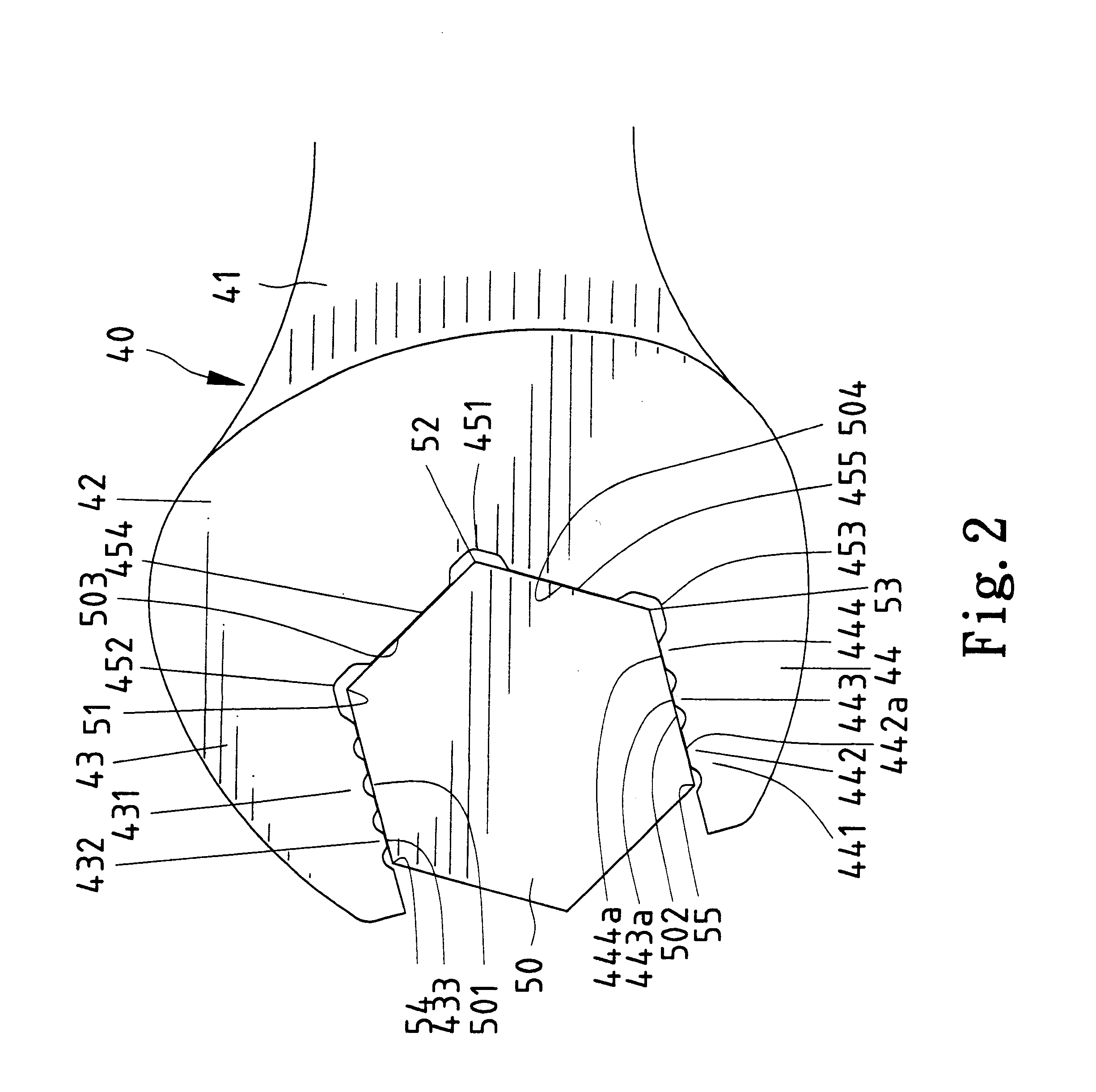
Referring to FIGS. 1 and 2, a wrench 40 according to the preferred embodiment of the present invention includes a head 42, a handle 41 extending from the head 42 in a direction and two jaws 43 and 44 extending from the head 42 in an opposite direction. A throat 45 is formed between the jaws 43 and 44.

The jaw 43 includes a serrated surface 431 consisting of four teeth 432 each including a crown 433.

Similarly, the jaw 44 includes a serrated surface 441 consisting of a first tooth 442, a second tooth 443 and a third tooth 444. The first tooth 442 includes a crown 442a. The second tooth 443 includes a crown 443a. The third tooth 444 includes a crown 444a. The crown 442a of the first tooth 442 is longer than the crown 444a of the third tooth 444. The crown 444a of the third tooth 444 is longer than the crown 443a of the second tooth 443. The crown 443a of the second tooth 443 is longer than the crown 433 of each tooth 432.

The throat 45 includes two flat surfaces 454 and 455 corresponding...


PUM


Abstract

A wrench includes a head and a handle extending from the head in a direction. The head includes two jaws extending from the head in an opposite direction and a throat formed between the jaws. Each of the jaws includes a contact surface for contact with a facet of a head of a bolt. The contact surface of at least one of the jaws includes a plurality of teeth. The throat defines a central recess for receiving a corner of the head of the bolt. The head may define a recess between the throat and each of the jaws. The throat may include two flat contact surfaces for contact with two adjacent facets of the head of the bolt. The central recess defined in the throat is positioned between the flat contact surfaces of the throat.

Description

BACKGROUND OF INVENTION1. Field of InventionThe present invention relates to a wrench.2. Related Prior ArtReferring to FIG. 3, a conventional wrench 10 includes a head (not numbered), a handle 11 extending from the head in a direction, and two jaws 12 and 13 extending from the head in an opposite direction. The jaw 12 includes a flat surface 121. The jaw 13 includes a flat surface 131. A throat 14 is formed between the jaws 12 and 13. The throat 14 includes an arched surface (not numbered). In use, the head of the wrench 10 is engaged with a head of a bolt 20. The flat surfaces 121 and 131 contact two facets 21 and 22 of the head of the bolt 20, respectively. Two problems are encountered in use of the wrench 10. Firstly, slipping happens between the flat surface 121 and the facet 21 and between the flat surface 131 and the facet 22. Secondly, a corner 23 between two facets 26 and 27 may be worn out by the arched surface of the throat 14, and corners 24 and 25 by the flat surfaces 12...

Claims


Application Information

Patent Timeline
Patent Type & Authority Patents(United States)
IPC IPC(8): B25B13/08B25B13/00
CPCB25B13/08
Inventor HUANG, HSIU-CHING
Owner LIN CLARE
Why Eureka
Try Eureka