Hydraulic clutch with a turbine torsional vibration damper

a technology of vibration damper and turbine, which is applied in the direction of interengaging clutches, fluid couplings, gearing, etc., can solve the problem of requiring a particularly small installation spa

Inactive Publication Date: 2004-07-06
ZF FRIEDRICHSHAFEN AG
View PDF8 Cites 10 Cited by
  • Summary
  • Abstract
  • Description
  • Claims
  • Application Information

AI Technical Summary

Benefits of technology

Further, by means of this step, each of the two sliding bearings can be designed, in itself, in an optimal manner for its respective task without influencing the other sliding bearing.
When the holding clamp has a radial bend, the construction volume of the hydraulic clutch can be reduced even more while retaining the same efficiency.

Problems solved by technology

When this rolling bearing is constructed as a needle bearing, it requires a particularly small installation space, especially axial installation space.

Method used


Image

  • Hydraulic clutch with a turbine torsional vibration damper
  • Hydraulic clutch with a turbine torsional vibration damper
  • Hydraulic clutch with a turbine torsional vibration damper

Examples


Embodiment Construction

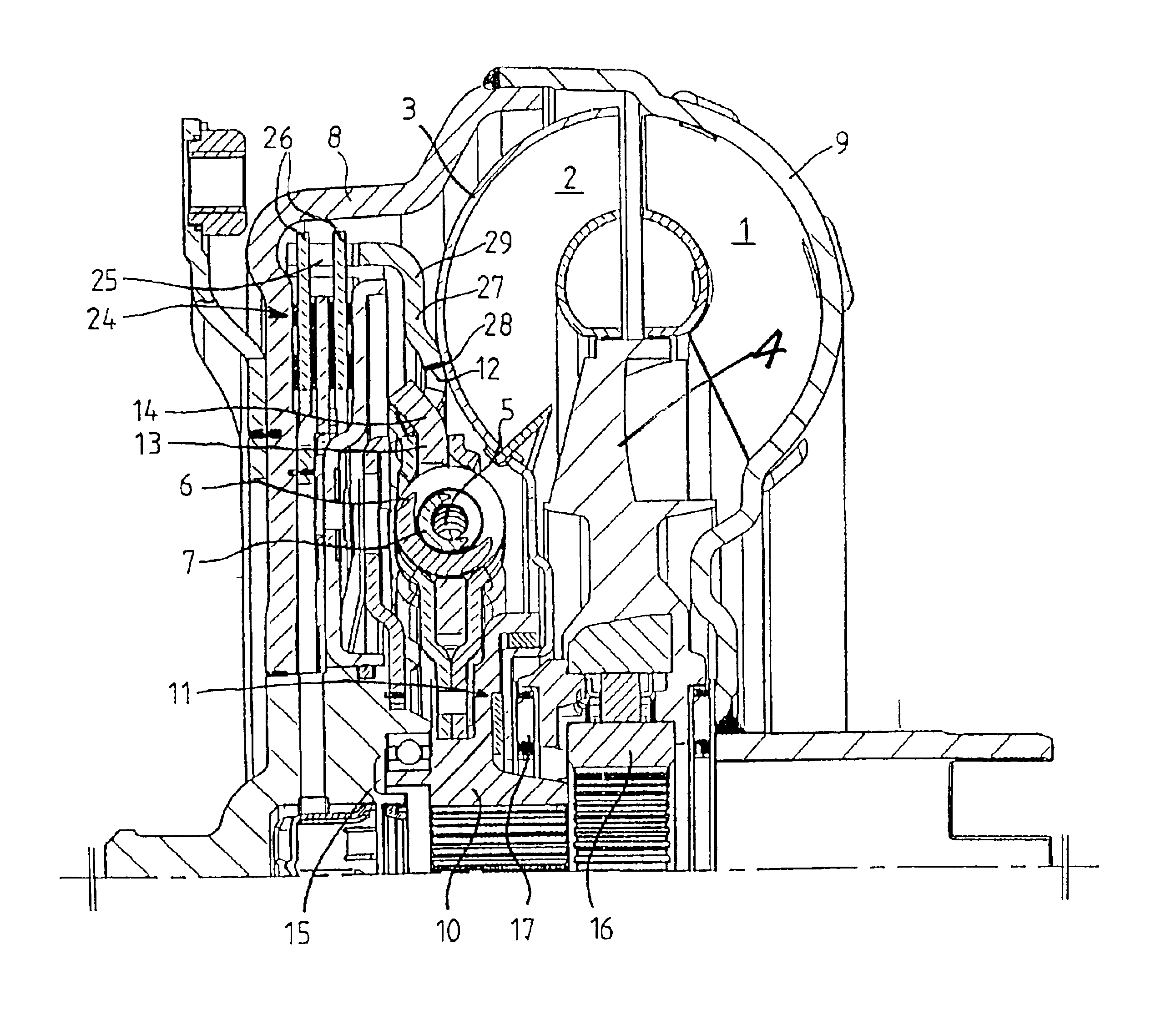
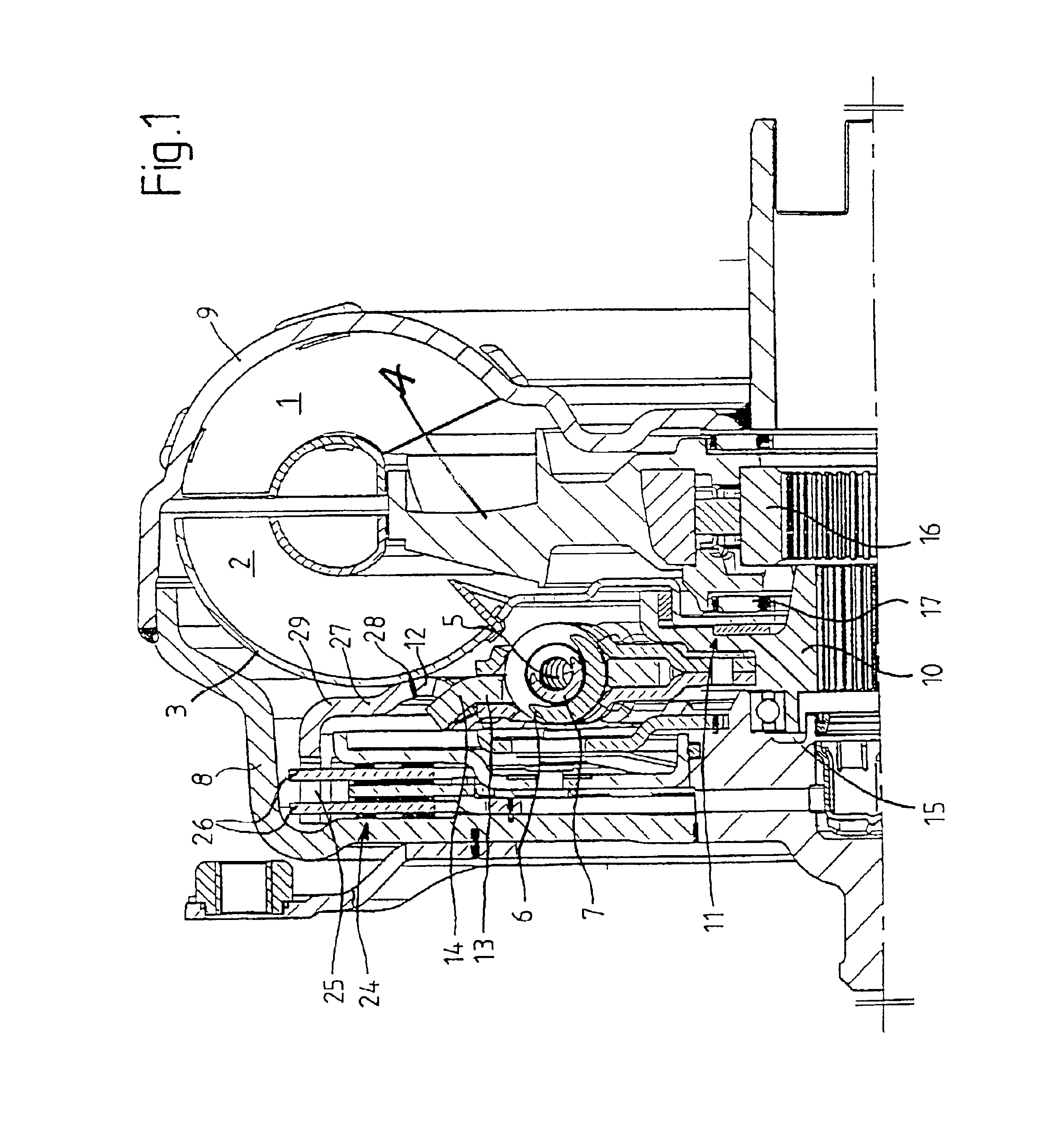
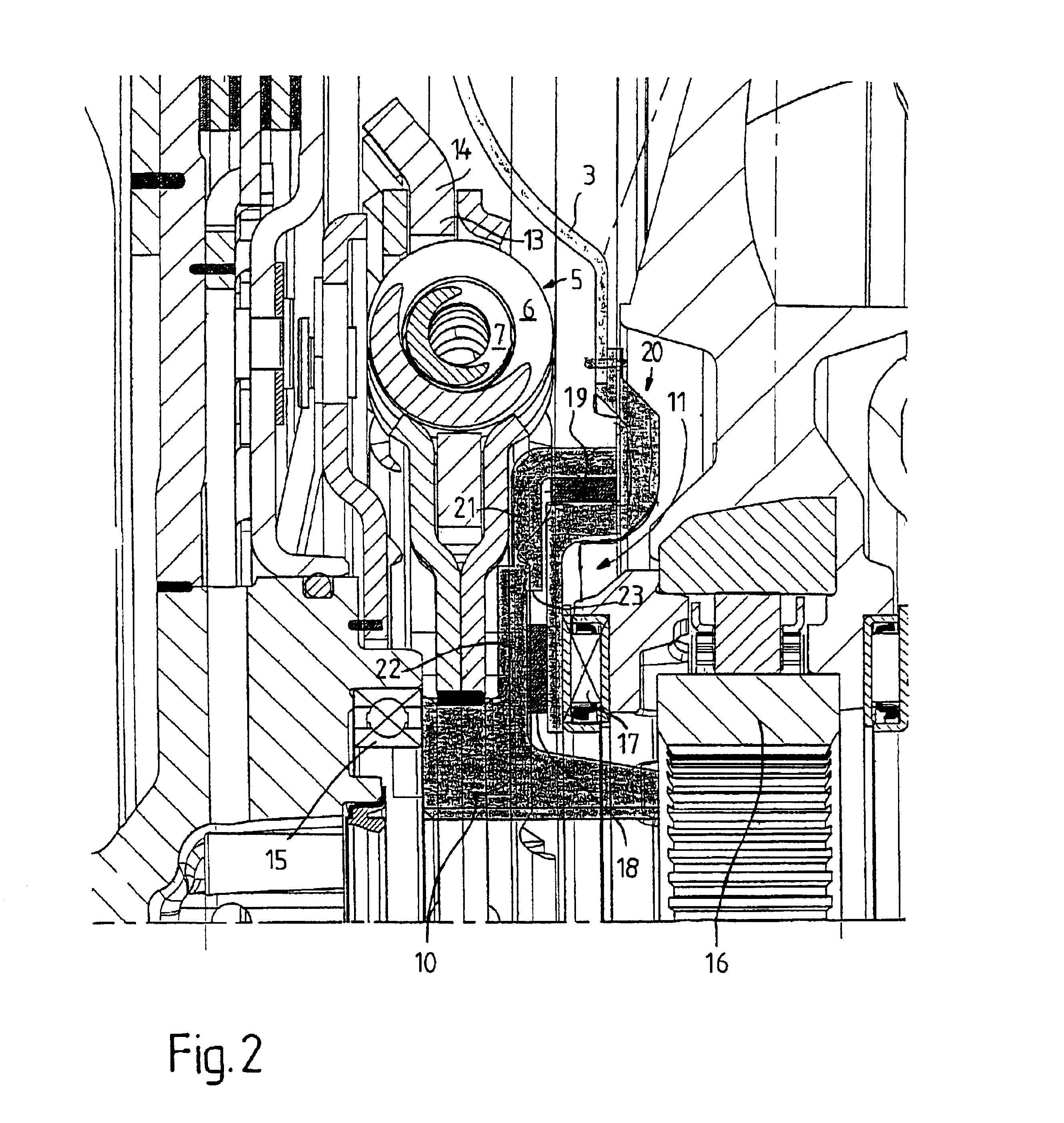
According to FIG. 1, a torque converter has an impeller wheel 1, a turbine wheel 2 with a turbine wheel shell 3, a stator wheel 4 and a torsional vibration damper 5. As can be seen, the torsional vibration damper 5 is arranged on the radial inner side. It has two spring assemblies 6, 7 which are nested concentrically one inside the other.

As is generally common, a drive shaft, not shown for the sake of clarity, e.g., the crankshaft of an internal combustion engine, can be connected to a drive-side housing element 8 so as to be fixed with respect to rotation relative to it. The drive-side housing element 8 is connected, e.g., welded, to an impeller wheel shell 9. The turbine wheel 2 can be driven by the impeller wheel 1.

The torsional vibration damper is arranged on a turbine wheel hub 10 so as to be fixed with respect to rotation relative to it. The turbine wheel hub 10 can be driven by the turbine wheel 2 by means of the torsional vibration damper and the turbine wheel shell 3.

The tu...


PUM


Abstract

A hydraulic clutch has an impeller wheel, a turbine wheel with a turbine wheel shell, and a torsional vibration damper. The turbine wheel is drivable by the impeller wheel. The turbine wheel shell is mounted in an axial and radial sliding bearing so as to be rotatable with respect to a turbine wheel hub. The torsional vibration damper is arranged on the turbine wheel hub so as to be fixed with respect to rotation relative to it. The turbine wheel hub is drivable by the turbine wheel via the turbine wheel shell and the torsional vibration damper. The turbine wheel shell acts on the torsional vibration damper via a connection element. The axial sliding bearing is spatially offset with respect to the radial sliding bearing.

Description

1. Field of the InventionThe present invention is directed to a hydraulic clutch with an impeller wheel, a turbine wheel with a turbine wheel shell, and a torsional vibration damper.2. Description of the Related ArtDE 43 33 562 A1 discloses a hydraulic clutch of the type mentioned above wherein the turbine wheel is drivable by the impeller wheel, and the turbine wheel shell is mounted in an axial and radial sliding bearing so as to be rotatable with respect to a turbine wheel hub. The torsional vibration damper is arranged on the turbine wheel hub so as to be fixed with respect to rotation relative to it and the turbine wheel hub is drivable by the turbine wheel via the turbine wheel shell and the torsional vibration damper. The turbine wheel shell acts on the torsional vibration damper via a connection element.The hydraulic clutch of the prior art already operates quite satisfactorily, but is still capable of improvement.It is the object of the present invention to design a hydraul...

Claims


Application Information

Patent Timeline
Patent Type & Authority Patents(United States)
IPC IPC(8): F16H45/00F16H45/02
CPCF16H45/02F16H2045/0247F16H2045/0284
Inventor BAUER, THOMASFREY, PETERRONNEBECK, RALF
Owner ZF FRIEDRICHSHAFEN AG
Why Eureka
Try Eureka