Container for a stack of interfolded tissue sheets and a method for manufacturing such a container

a technology of tissue sheets and containers, which is applied in the direction of containers, rigid containers, pile separation, etc., can solve the problem of wrinkles on the uppermost tissue, and achieve the effect of simple and convenient manufacturing

Inactive Publication Date: 2004-07-06
SCA HYGIENE PROD AB
View PDF13 Cites 28 Cited by
  • Summary
  • Abstract
  • Description
  • Claims
  • Application Information

AI Technical Summary

Benefits of technology

The present invention offers a simple and expedient means of solving the problem of dispensing a flat tissue sheet from a stack of interfolded tissue sheets which are packed in a container having a dispensing opening. In a preferred embodiment, the opening is wider than the width of said tissue sheets. The invention will, however, also be applicable for openings of equal or narrower width than the width of the tissue sheets.
According to a further embodiment, said slot is an insert attached to the top wall, which insert covers the opening. The insert may be made from a plastic material, such as polypropylene, in order to give both sufficient flexibility and stiffness. The flexibility and stiffness may also be varied by using plastic materials of different thickness.
The opening can be used to control the flexibility and stiffness of the fingers arranging the edge of the opening at a predetermined distance from said fingers. A wide opening positioned away from the base of the fingers will give high flexibility and low stiffness. On the other hand, an opening having an edge overlapping the recesses of opposing fingers will give low flexibility and high stiffness. In this way the fingers may be adapted for tissues of different materials and materials of different thickness.
In a further embodiment, any two consecutive pairs of opposing fingers should co-operate independently. Hence, a cut line between adjacent fingers of two pairs of opposing fingers should only have one inflection point. In the vicinity of the inflection point, the cut line should be straight or have a comparatively large curvature. In this way it is ensured that each pair of opposing fingers can move and flex together without interference from adjacent pairs of fingers.

Problems solved by technology

However, a problem arises when it is desired to dispense a flat tissue sheet from the stack of tissue sheets.
In ordinary boxes of this type, the uppermost tissue is usually wrinkled when it is presented to the user through the opening in the box.
Although a wider opening in the box solves the problem with tissues being wrinkled as they are pulled out of the box, it creates a further problem with tissues falling back into the box where they are inaccessible for the user.

Method used


Image

  • Container for a stack of interfolded tissue sheets and a method for manufacturing such a container
  • Container for a stack of interfolded tissue sheets and a method for manufacturing such a container
  • Container for a stack of interfolded tissue sheets and a method for manufacturing such a container

Examples


second embodiment

FIG. 9 shows a plan view of a top wall 1 provided with an opening 4 as defined in relation to FIG. 1B. In this second embodiment of the fingers, the shape has been modified in order to allow the tips to be enlarged further. The embodiment shown in FIG. 9 is provided with fingers wherein the centreline C.sub.F for the cut line of the slot is a straight line coinciding with both the main axis A.sub.M of the opening 4 and the central longitudinal axis A.sub.X of the top wall 1. The fingers 110, 111; 112, 113; 114, 115; 116, 117; 118, 119; 120, 121 have their main axes A1-A12 placed at substantially the same angle .alpha. relative to the longitudinal axis A.sub.X. According to this embodiment, the minimum width W.sub.Min, at right angles to the main axis of each finger occurs in an inner section. Similarly, the maximum width W.sub.Max, at right angles to the main axis of each finger occurs in an outer section. The minimum width W.sub.Min and the maximum width W.sub.Max occur on opposite...

third embodiment

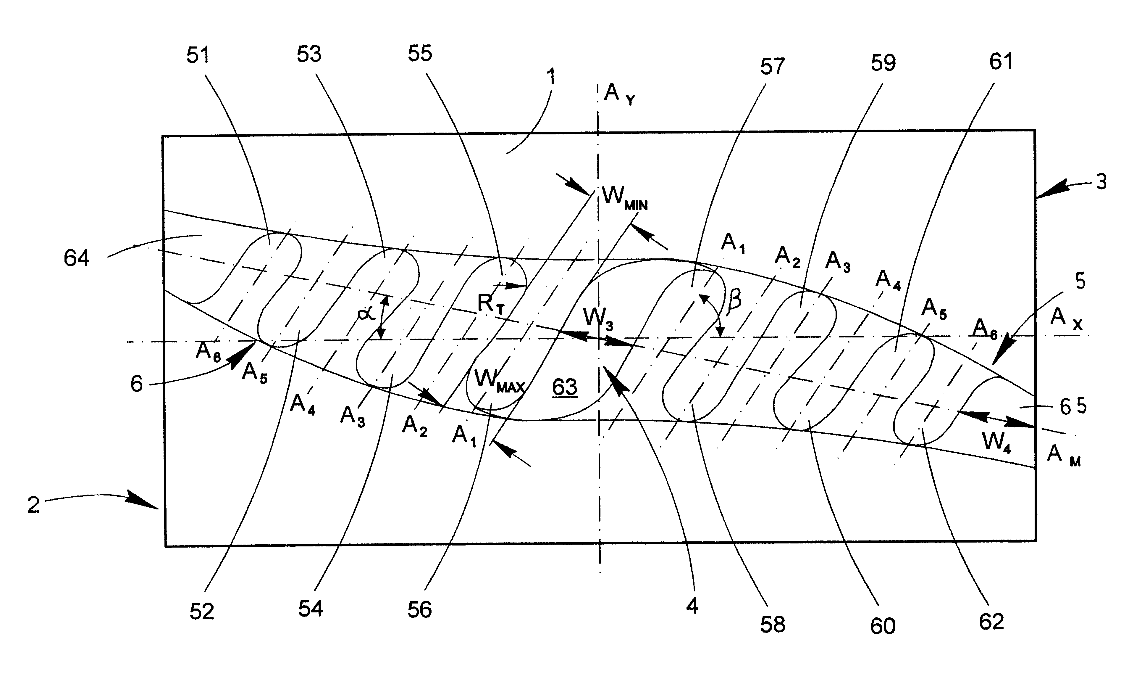
FIG. 10 shows a plan view of a top wall 1 provided with an opening 4 as defined in relation to FIG. 1A. This figure shows the fingers, which have been given a shape that allows a relatively large tip radius without enlarging the surface area of an outer section of the finger. The opening 4 in this embodiment is provided with fingers having a centreline C.sub.F for the cut line of the slot is a straight line coinciding with both the main axis A.sub.M of the opening 4 and the central longitudinal axis A.sub.X of the top wall 1. The fingers 130, 131; 132, 133; 134, 135; 136, 137; 138, 139; 140, 141 have their main axes A.sub.1 -A.sub.6 placed at substantially the same angle .alpha. relative to the longitudinal axis A.sub.X.

In order to increase the width of an outer section of the fingers, each of the tips of a pair of adjacent, opposing fingers have been angled towards each other. This has been achieved by curving or bending the cut line of the outer section of each tip of a co-operati...


PUM

PropertyMeasurementUnit
angleaaaaaaaaaa
widthaaaaaaaaaa
widthsaaaaaaaaaa

Abstract

The invention relates to a container for a collection of interfolded or mechanically connected tissue-sheets, the container having a generally planar bottom wall and a top wall and a pair of side walls and a par of end walls connecting the bottom wall with the top wall and an opening provided in at least the top wall for the removal of the tissue-sheets from the container, the stack of interfolded tissue-sheets being placed in the container with at least a pair of edges of a lowermost tissue-sheet placed on the bottom wall and an uppermost tissue-sheet placed near or in contact with the top wall and adjacent to the opening in the top wall. The opening is provided with elongated projections extending from opposite sides of the opening, wherein each projection in an initial position extends across the opening in the plane of the top wall and is positioned adjoining at least one opposing projection, and the projections are arranged in co-operating pairs, wherein each projection has at least one inner section having a smaller width than an adjacent outer section.

Description

TECHNICAL AREAThe invention pertains to a stack of interfolded tissue-sheets packed in a container, said container having a generally planar bottom wall and a top wall and side walls connecting the bottom wall with the top wall and an opening provided in at least one wall for the removal of said tissue-sheets from the container, said stack of interfolded tissue-sheets being placed in said container with at least the edges of a lowermost tissue-sheet placed on the bottom wall and an uppermost tissue-sheet placed near or in contact with the top wall and adjacent to the opening in the top wall.Soft tissue sheets such as facial tissue sheets are commonly offered as a stack of tissue sheets packed in a dispensing box. The dispensing box has an opening through which the user pulls the tissue sheets. In order to facilitate the removal of the tissue sheets from the dispensing box, the tissue sheets are interfolded, which means that the tissue sheets are folded into one-another, so that they...

Claims


Application Information

Patent Timeline
Patent Type & Authority Patents(United States)
IPC IPC(8): B65D83/08
CPCB65D83/0805
Inventor MORIN, EMMANUELLECHIHANI, THAMI
Owner SCA HYGIENE PROD AB
Why Eureka
Try Eureka