Check patentability & draft patents in minutes with Patsnap Eureka AI!

Optical disc having land pre-pits and variable groove depths

a technology of optical discs and grooves, applied in the field of optical disc substrates, can solve the problems of difficult to obtain stable tracking signals, difficult to obtain arbitrary width of grooves, and unsuitable for recording in higher liner velocity,

Inactive Publication Date: 2004-11-16
TAIYO YUDEN KK +1
View PDF12 Cites 14 Cited by
  • Summary
  • Abstract
  • Description
  • Claims
  • Application Information

AI Technical Summary

Problems solved by technology

A width of groove also depends on laser beam intensity, so that it is extremely hard to obtain an arbitrary width of groove.
Further, a shape of groove obtained becomes approximately a V shaped one, so that a stable tracking signal can hardly be obtained.
Furthermore, a recording power for recording a signal in a groove is necessary to be more powerful than that for recording in a conventional groove having a rectangular bottom, so that such a V shaped groove is a shape of unsuitable for recording in higher liner velocity.

Method used


Image

  • Optical disc having land pre-pits and variable groove depths
  • Optical disc having land pre-pits and variable groove depths
  • Optical disc having land pre-pits and variable groove depths

Examples


embodiment

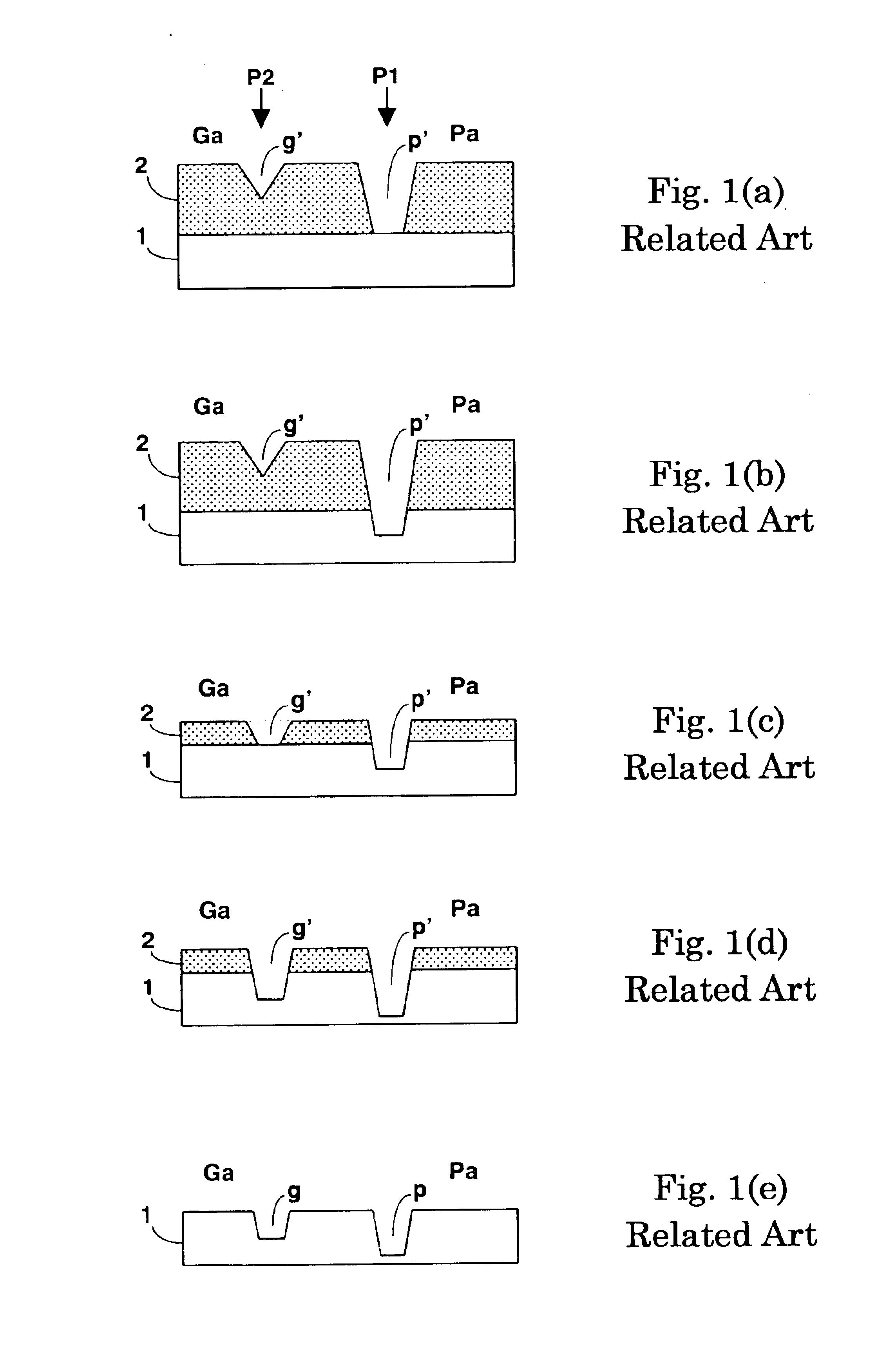
In order to solve the problems of the prior art and the related art, the present invention provide an optical disc and a manufacturing method of an optical disc master for manufacturing the optical disc substrate.

FIGS. 4(a) through 4(e) are exemplary drawings showing a fundamental manufacturing process of an optical disc master according to an embodiment of the present invention.

FIG. 5(a) is a fragmentary plan view showing a vicinity of a land pre-pit (LPP) on a optical disc substrate formed through a forming process of the photoresist pattern by a manufacturing method according to the embodiment of the present invention.

FIG. 5(b) is a cross sectional view of the photoresist pattern on a glass substrate in the middle of the manufacturing process of the optical disc substrate shown in FIG. 5(a) corresponding to be taken substantially along line A--A of FIG. 5(a).

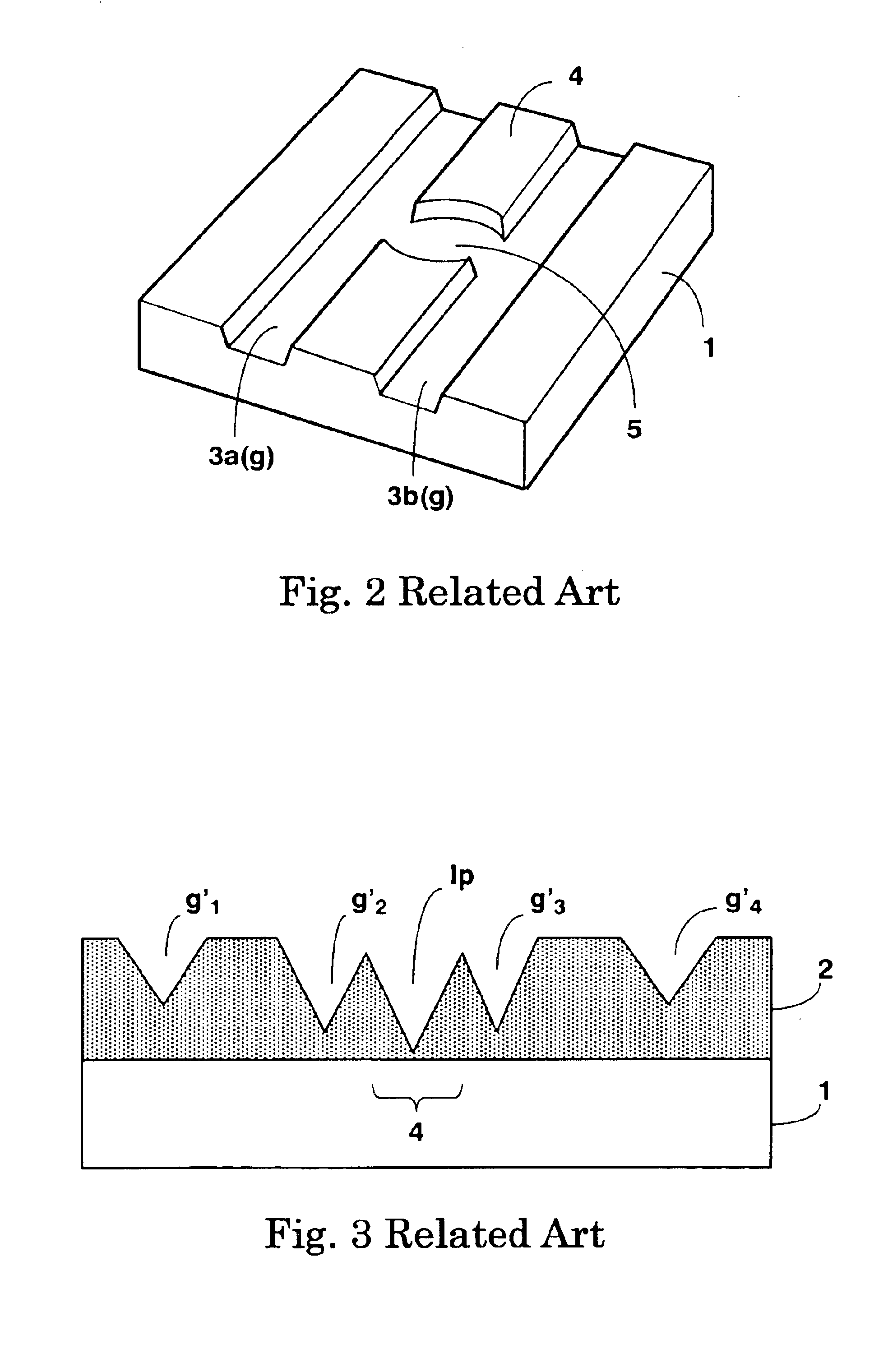
In FIG. 5(a), reference sings 13a through 13c are groove sections, 15 is a land pre-pit (LPP) section, 16 is a part of the ...


PUM

PropertyMeasurementUnit
thickaaaaaaaaaa
thicknessaaaaaaaaaa
depthaaaaaaaaaa

Abstract

When an LPP (land pre-pit) is formed between shallow grooves or shallow pits, the LPP is formed on a land existing between the shallow grooves or the shallow pits. Further, the LPP is formed in a position displaced from a centerline of the land in the radial direction by a predetermined amount. Furthermore, a laser beam power utilized for forming a shallow groove or a shallow pit adjacent to the LPP is reduced so as to be lower than a regular laser beam power.

Description

1. Field of the InventionThe present invention relates to an optical disc substrate and a manufacturing method of an optical disc master for manufacturing the optical disc substrate.2. Description of the Prior ArtThere existed various types of optical discs such as a read only type, a recordable type and a rewritable type. An optical disc, which is provided with a read only area and a recordable area enabling to be recorded by a user in one substrate, has been proposed and practiced. In an optical disc having a pit area to be a read only area and a groove area to be a recordable area, generally, a pit depth is set to .lambda. / 4n, which is the maximum amplitude of a sum signal of a reproduced signal, wherein .lambda. is a wavelength of a laser beam for recording and reproducing and "n" is a refractive index of a substrate of the optical disc. On the other hand, a groove depth is set to .lambda. / 8n, which is the maximum amplitude of a differential signal of a tracking signal. In order...

Claims


Application Information

Patent Timeline
Patent Type & Authority Patents(United States)
IPC IPC(8): G11B7/013G11B7/26G11B7/007
CPCG11B7/007G11B7/261G11B7/24085G11B7/00718
Inventor DENO, TAKAYUKISHIMOMAI, KENICHIASANUMA, TOYOHITOMATSUMOTO, TSUTOMUTSUJI, FUMITAKA
Owner TAIYO YUDEN KK
Features
  • R&D
  • Intellectual Property
  • Life Sciences
  • Materials
  • Tech Scout
  • Unparalleled Data Quality
  • Higher Quality Content
  • 60% Fewer Hallucinations
Learn More