Rim illuminating device

a technology of illuminating device and rim, which is applied in the direction of lighting safety devices, transportation and packaging, lighting and heating equipment, etc., can solve the problems of difficult use, complicated conventional devices, and the inability to disclose a new illuminating device for motor vehicles, and achieve the effect of convenient mounting and removal

Inactive Publication Date: 2005-03-29
MORTON KENNY F
View PDF17 Cites 1 Cited by
  • Summary
  • Abstract
  • Description
  • Claims
  • Application Information

AI Technical Summary

Benefits of technology

Still another object of the present invention is to provide a new rim illuminating device for removably mount to a rim of a motor vehicle in order to create a visual effect when the motor vehicle is moving. In particular, the lights provide a visual effect that makes a motor vehicle appear as though it is floating.
Still yet another object of the present invention is to provide a new illuminating device that unlike the conventional devices is easily mountable and removable from a wheel rim of a motor vehicle.
Even still another object of the present invention is to provide a new illuminating device that provides a user with light if the user needs to work on a flat tire.

Problems solved by technology

While these devices fulfill their respective, particular objectives and requirements, the aforementioned patents do not disclose a new illuminating device for motor vehicles.
The conventional devices are complicated and difficult to use.

Method used


Image

  • Rim illuminating device
  • Rim illuminating device
  • Rim illuminating device

Examples


Embodiment Construction

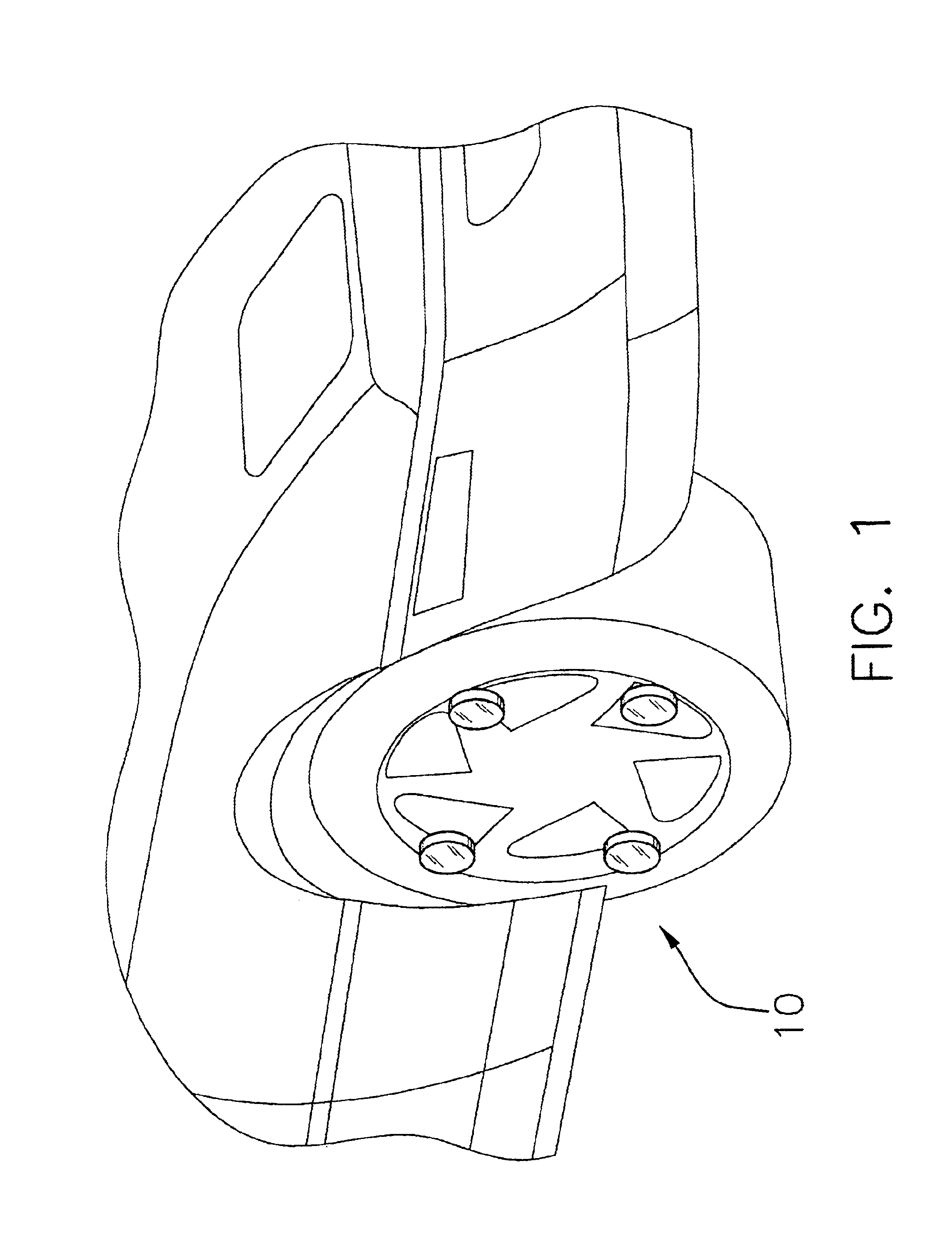
With reference now to the drawings, and in particular to FIGS. 1 through 4 thereof, a new rim illuminating device embodying the principles and concepts of the present invention and generally designated by the reference numeral 10 will be described.

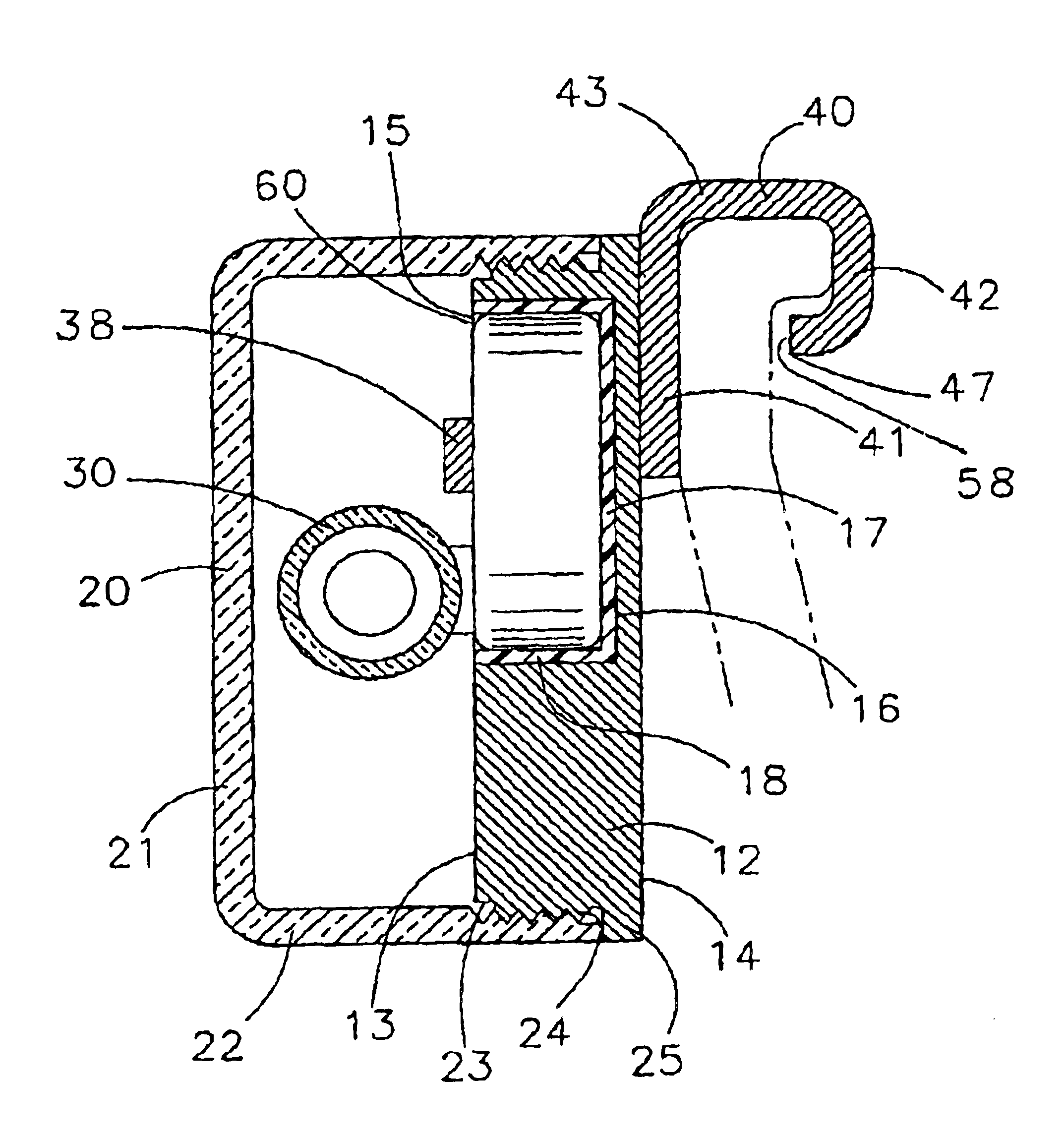
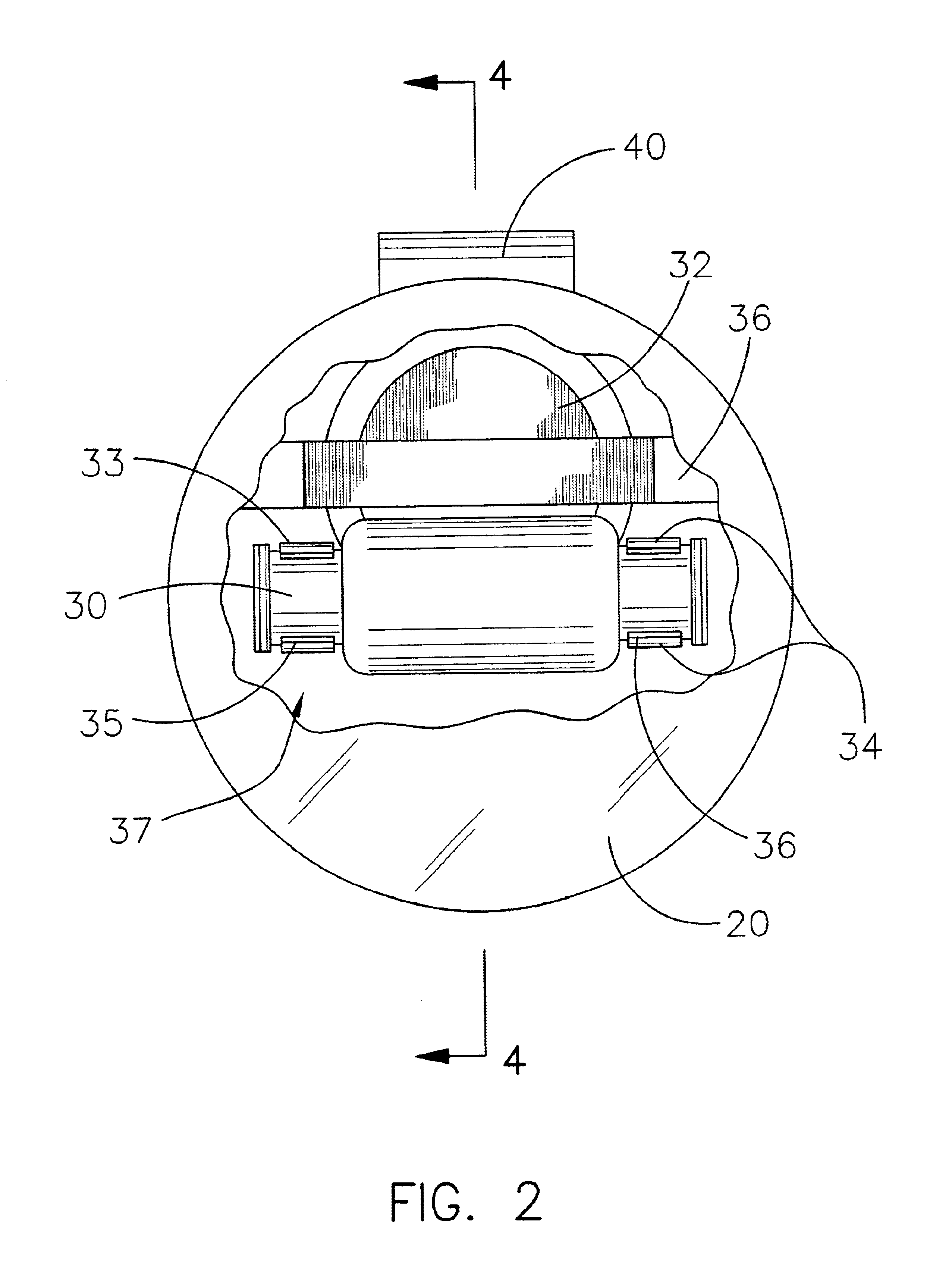
As best illustrated in FIGS. 1 through 4, the rim illuminating device 10 generally comprises a housing 12 that has a first surface 13 and a second surface 14. A cover 20 is removably mounted to the first surface 13 of the housing 12 for covering the first surface 13 of the housing 12. An illuminating member 30 is mounted to the first surface 13 of the housing 12 for emitting light. A power supply 32 is mounted to the housing 12 and is electrically connected to the illuminating member 30 for selectively providing power thereto. A coupling member 40 is mounted to the second surface 14 of the housing 12 for removably mounting the housing 12 to a rim of a motor vehicle.

As illustrated in FIG. 4, the first surface 13 of the housing 12 may have a...


PUM


Abstract

A rim illuminating device for removably mounting to a rim of a motor vehicle in order to create a visual effect when the motor vehicle is moving. The illuminating device includes a housing that has a first surface and a second surface. A cover is mounted to the first surface of the housing for covering the housing. An illuminating member is mounted to the first surface of the housing for emitting light. A power supply is mounted to the housing and electrically connected to the illuminating member for selectively providing power thereto. A coupling member is mounted to the second surface of the housing for removably mounting the housing to the rim of the vehicle.

Description

BACKGROUND OF THE INVENTION1. Field of the InventionThe present invention relates to illuminating accessories for motor vehicles and more particularly pertains to a new rim illuminating device for removably mount to a rim of a motor vehicle in order to create a visual effect when the motor vehicle is moving.2. Description of the Prior ArtThe use of illuminating accessories for motor vehicles is known in the prior art. More specifically, illuminating accessories for motor vehicles heretofore devised and utilized are known to consist basically of familiar, expected and obvious structural configurations, notwithstanding the myriad of designs encompassed by the crowded prior art which have been developed for the fulfillment of countless objectives and requirements.Known prior art includes U.S. Pat. No. 6,030,106; U.S. Pat. No. 4,881,153; U.S. Pat. No. 5,683,164; U.S. Pat. No. 4,430,692; U.S. Pat. No. Des. 332,441; U.S. Pat. No. 6,116,762.While these devices fulfill their respective, par...

Claims


Application Information

Patent Timeline
Patent Type & Authority Patents(United States)
IPC IPC(8): B60Q1/26
CPCB60Q1/326
Inventor MORTON, KENNY F.
Owner MORTON KENNY F
Why Eureka
Try Eureka