Modular link conveyor chain with rotatable article engaging assemblies

a technology of modular link and conveyor chain, which is applied in the field of conveyor chain, can solve the problems of increasing the risk of damage, not making provision for the efficient conveyance of articles in a different direction, and still exist limitations, so as to facilitate the movement of articles and reduce the backline pressure

Inactive Publication Date: 2005-04-05
SPAN TECH
View PDF24 Cites 43 Cited by
  • Summary
  • Abstract
  • Description
  • Claims
  • Application Information

AI Technical Summary

Benefits of technology

In accordance with a first aspect of the invention, a chain for intended use in moving one or more articles in at least a conveying direction and also permitting movement in a direction different from the conveying direction is provided. The chain comprises a plurality of modular links forming a conveying surface, at least one article engaging assembly also forming part of the conveying surface and including a body supporting at least one rotatably mounted cap, and a transverse connector connecting the modular links and rotatably supporting the body. As a result of this arrangement, the article engaging assembly may rotate in the conveying direction to provide low backline pressure for the articles and may facilitate article movement in the different direction through engagement with the rotatably mounted cap.
In accordance with a seventh aspect of the invention, a method of moving articles in a conveying direction is disclosed. The method comprises: (1) interconnecting a plurality of modular links forming a first row with a transverse connector having a longitudinal axis to partially form a chain; and (2) rotatably mounting at least one article engaging assembly on the connector, the assembly including at least one cap mounted for rotation about an axis generally transverse to the longitudinal axis. As a result, the conveying may be with low backline pressure, including in an accumulation mode, and the rotatable caps enable smooth and efficient article movement in a direction different from the conveying direction.

Problems solved by technology

However, no provision is made for the efficient conveyance of articles in a direction different from the conveying direction (e.g., directly transverse to it), as may be necessary when diversion onto a transfer or takeaway conveyor is needed.
Although forcibly moving lightweight or low-friction articles laterally across the chain is a possible solution, this increases the risk of damage, and really is not an, option when the articles are large or heavy, such as filled cartons, or have high-friction surfaces, such as tires.
Despite the seemingly advanced nature of this approach, limitations still exist.
With respect to the links including the recessed rollers, performance remains limited by the fact that the conveying ability is generally unidirectional.
This makes the arrangement not well-suited for use in environments where sanitation is the primary concern (such as the conveyance of articles comprising food products).
Another limitation is that the spherical balls are recessed such that only a small amount of the surface is available for engaging the articles, which would otherwise tend to drag on the stationary link forming the vast majority of the conveying surface.
Still another limitation is that the spherical balls may pop-out of the recesses under moderate shearing forces unless a separate cover is used.
Losing even a single ball not only renders the links ineffective for use as intended, but also adds to the maintenance expense.
The solution of providing a partial cover also complicates the overall assembly, adds to the manufacturing cost, and creates a protruding lip on which the articles may become caught during conveyance.
Aside from the likelihood of damage, a caught article may also result in a deleterious jam, causing downtime and requiring costly manual intervention to clear.
Since the entire surface of the spherical ball is exposed to the conveying surface during rotation, maintaining the proper lubrication in the corresponding recess to ensure smooth, reduced friction rolling contact may also be a limiting problem.

Method used


Image

  • Modular link conveyor chain with rotatable article engaging assemblies
  • Modular link conveyor chain with rotatable article engaging assemblies
  • Modular link conveyor chain with rotatable article engaging assemblies

Examples


Embodiment Construction

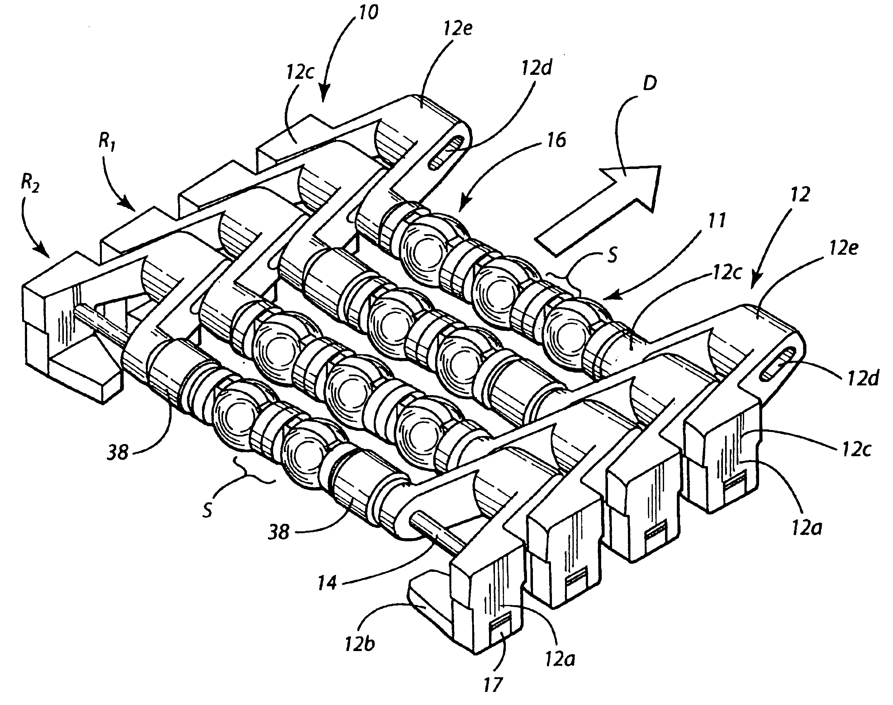
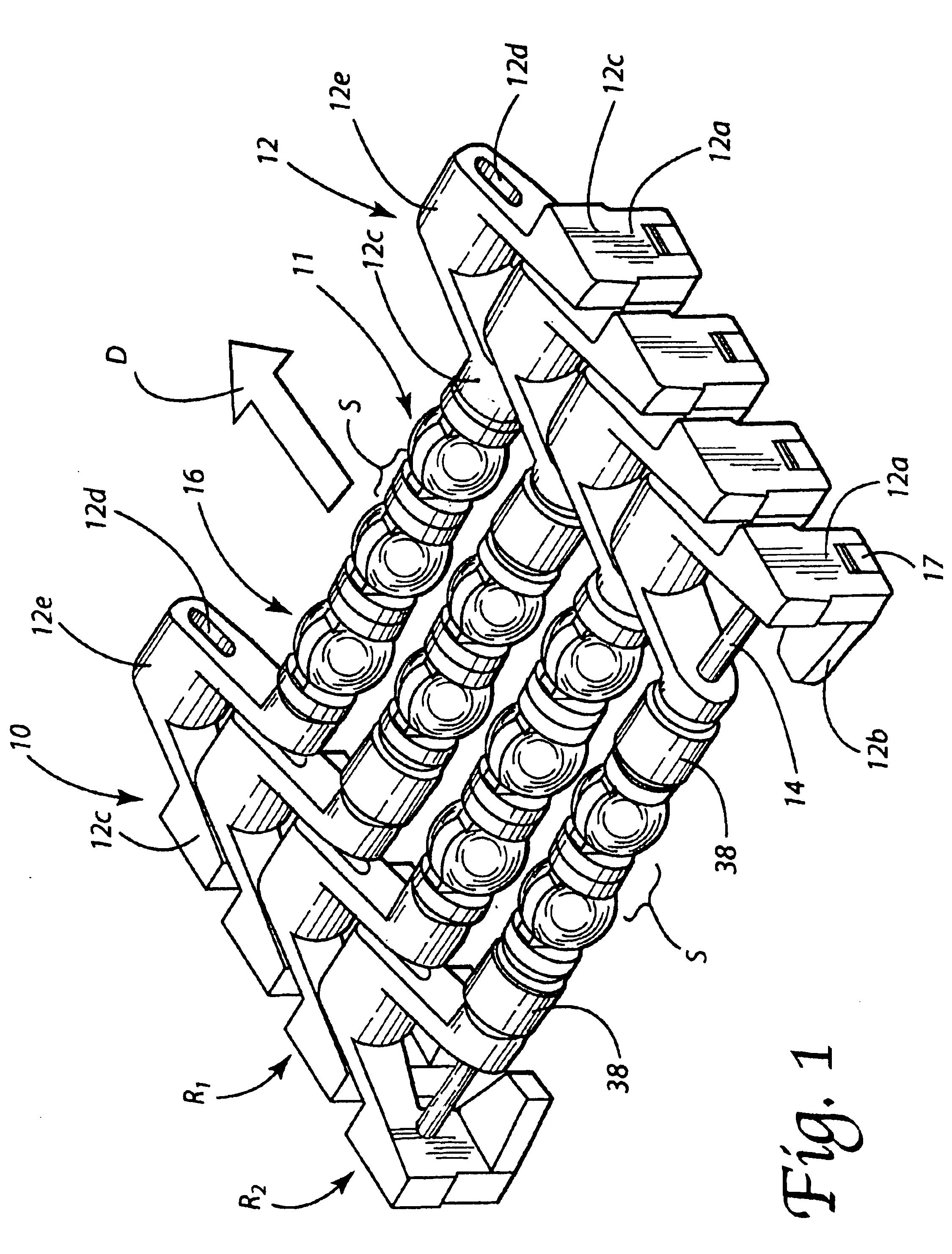
Reference is now made to FIG. 1, which depicts an overall arrangement of a conveyor chain 10 constructed in accordance with one embodiment of the present invention and defining a conveying surface 11 for engaging and supporting articles. In this particular embodiment, the chain 10 comprises or includes modular links in the form of side links 12 arranged in spaced apart rows, which thus partially create the conveying surface 11. The rows are interconnected by transverse connectors 14 carrying one or more article engaging assemblies 16. The construction and function of these assemblies 16 is outlined further in the following description.

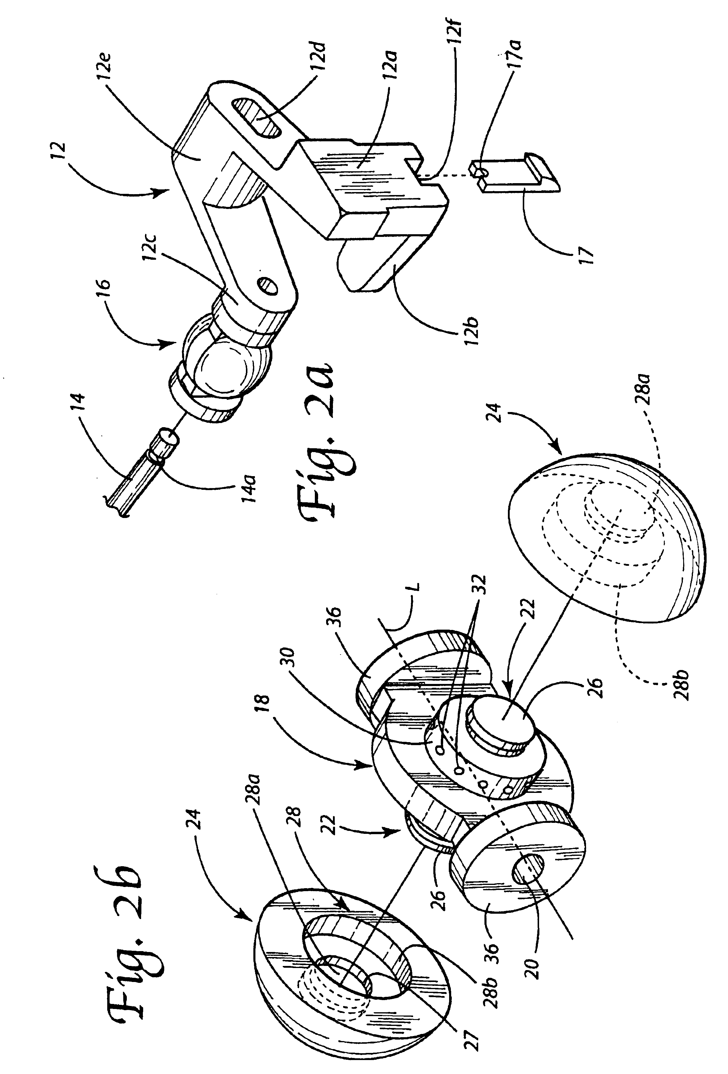
With regard to the side links 12, and as perhaps best understood with reference to FIG. 2a, each may be identical, or optionally may include an outer depending arm 12a and an inwardly projecting transverse tab 12b (thus creating different right handed or left handed side links, depending on the particular positioning). When present, the depending arm 1...


PUM


Abstract

Disclosed is a conveyor chain including modular links interconnected by an elongated transverse connector rotatably supporting article engaging assemblies including rotatably mounted caps. In one embodiment, the caps are provided with a generally spherical outer surface and are mounted for rotation about an axis generally transverse to a longitudinal axis of the connector. This arrangement thus allows for article conveyance with low backline pressure while facilitating the smooth and efficient diversion of an article in a direction generally transverse to the direction of chain movement through engagement with the caps. The chain may be of fixed length, or alternatively may be adapted to undergo side-flexing movement to negotiate curves or bends when driven in an endless path over a support structure forming part of a conveyor system, as well as longitudinal expansion and compression. One or more spacers may laterally offset the article engaging assemblies on alternating connectors forming the chain.

Description

TECHNICAL FIELDThis invention relates generally to the conveyor art and, more particularly, to a conveyor chain especially adapted for use in situations where moving articles in both a conveying direction and a direction different from the conveying direction may be desirable.BACKGROUND OF THE INVENTIONThe use of modular link conveyors in industry enjoys increasing popularity. Particularly for conveying food articles or consumer products, especially in packages or in semi-packaged form, the modular link conveyor represents the overwhelming choice of those in the industry looking for a long-lasting, low cost conveying solution. In the recent past, significant advances in the development of such have been made so as to provide more efficient handling of an even larger variety of food articles, packages and containers, as well as other types of articles and products.One of the most popular types of modular link conveyor systems on the market today, if not the most popular, is manufactu...

Claims


Application Information

Patent Timeline
Patent Type & Authority Patents(United States)
IPC IPC(8): B65G17/32B65G39/00B65G39/02B65G17/06
CPCB65G17/063B65G39/025B65G17/32B65G17/24
Inventor LAYNE, JAMES L.
Owner SPAN TECH
Why Eureka
Try Eureka