MPEG encoder control protocol for on-line encoding and MPEG data storage

a control protocol and encoder technology, applied in the field of processing and storage of compressed visual data, can solve the problems of buffer overflow, uncompressed audio and video splicing, and uncompressed audio/visual splicing,

a control protocol and encoder technology, applied in the field of processing and storage of compressed visual data, can solve the problems of buffer overflow, uncompressed audio and video splicing, and uncompressed audio/visual splicing,

US6907081B2Inactive Publication Date: 2005-06-14EMC IP HLDG CO LLC

Image

  • MPEG encoder control protocol for on-line encoding and MPEG data storage
  • MPEG encoder control protocol for on-line encoding and MPEG data storage
  • MPEG encoder control protocol for on-line encoding and MPEG data storage

Examples


Embodiment Construction

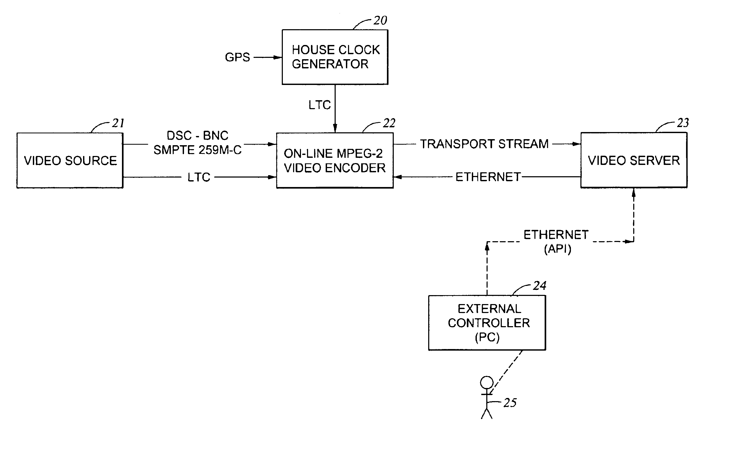
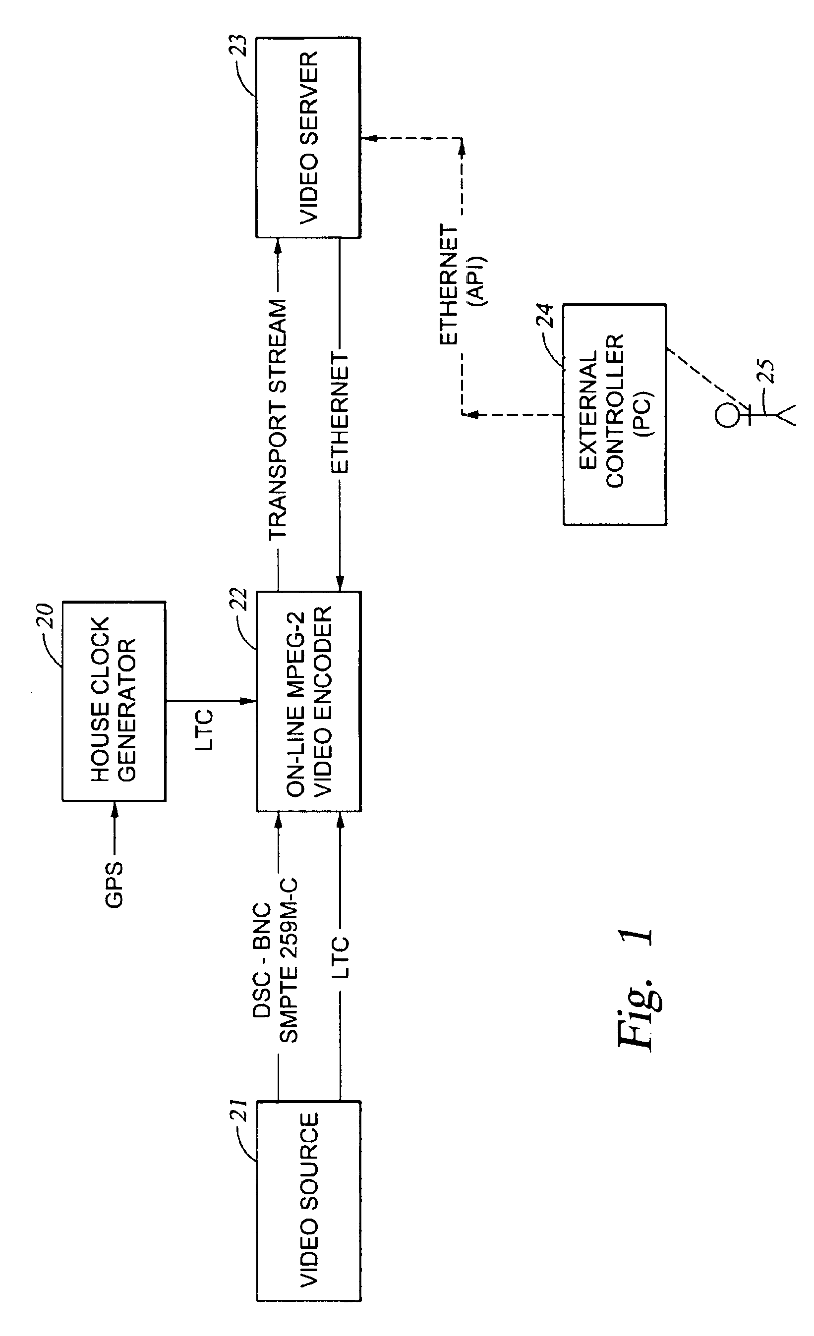
[0073]With reference to FIG. 1, there is shown a digital video recording system including a video source 21, an on-line MPEG-2 video encoder 22, a video server 23, an external controller 24, and a house clock generator 20 synchronized to a global positioning system (GPS) clock signal. As used herein, the term “on-line” is intended to be synonymous with “real-time.” The video source 21, such as a TV camera, video tape deck, or video disk player, provides a digital video signal over a digital serial channel (DSC) using a coaxial cable connection (BNC). For example, the video source may include an NTSC or PAL composite video signal, or a digital serial channel compliant with the serial digital interface (SDI) standard, and in particular the International Telecommunications Union standard ITU-R-656 or the SMPTE standard RS259. The on-line MPEG-2 video encoder 22 provides an MPEG-2 Transport Stream (TS) to the video server 23. The video server 23 is a storage system for storing video cli...


PUM


Abstract

Coded video from an on-line MPEG video encoder is stored as a clip in a video server or is otherwise received in the video server and prepared or used for splicing. In order to reduce apparent frame inaccuracy that may result from the splicing process, the on-line MPEG video encoder and the server are coordinated so that the group-of-picture (GOP) structure in the encoder provides specified In-points and Out-points that are valid and desirable for splicing. An encoder control protocol is also provided for remote control of the on-line MPEG video encoder in order to coordinate the on-line MPEG video encoder with the video server.

Description

[0001]A portion of the disclosure of this patent document contains computer commands to which the claim of copyright protection is made. The copyright owner has no objection to the facsimile reproduction by any person of the patent document or the patent disclosure, as it appears in the U.S. Patent and Trademark Office patent file or records, but reserves all other rights whatsoever.BACKGROUND OF THE INVENTION[0002]1. Field of the Invention[0003]The present invention relates to processing and storage of compressed visual data, and in particular the on-line encoding of MPEG data for storage, splicing, or other processing in a video server.[0004]2. Background Art[0005]It has become common practice to compress audio / visual data in order to reduce the capacity and bandwidth requirements for storage and transmission. One of the most popular audio / video compression techniques is MPEG. MPEG is an acronym for the Moving Picture Experts Group, which was set up by the International Standards ...

Claims


Application Information

Patent Timeline
14 Jun 2005
Publication
US6907081B2
IPC
G06T9/00; H04N7/24; H04N7/26; H04N21/234; H04N21/44; H04N21/845
CPC
H04N21/23412; H04N21/23424; H04N19/87; H04N21/8455; H04N19/46; H04N21/44016
Inventors
MANTCHALA, RAYMOND; FORECAST, JOHN