Optical illumination system and image projection system including the same

a technology of optical illumination and image projection, applied in the direction of electric lighting, lighting and heating equipment, instruments, etc., can solve the problems of adversely affecting image contrast and increasing manufacturing costs, and achieve the effects of reducing manufacturing costs, removing degradation, and simple structur

Inactive Publication Date: 2005-06-21
SAMSUNG ELECTRONICS CO LTD
View PDF8 Cites 9 Cited by
  • Summary
  • Abstract
  • Description
  • Claims
  • Application Information

AI Technical Summary

Benefits of technology

[0014]In order to solve the above and/or other problems, it is an aspect of present invention to provide an optical illumination system with a simple structure so as to

Problems solved by technology

Thus, difficulties in fabrication and assembling the total reflection prism degrade manufacturing and assembling capabilities, thus increasing manufacturing costs.
The light reflected off a

Method used


Image

  • Optical illumination system and image projection system including the same
  • Optical illumination system and image projection system including the same
  • Optical illumination system and image projection system including the same

Examples


Embodiment Construction

[0029]Reference will now be made in detail to the embodiments of the present invention, examples of which are illustrated in the accompanying drawings, wherein like reference numerals refer to the like elements throughout. The embodiments are described below in order to explain the present invention by referring to the figures.

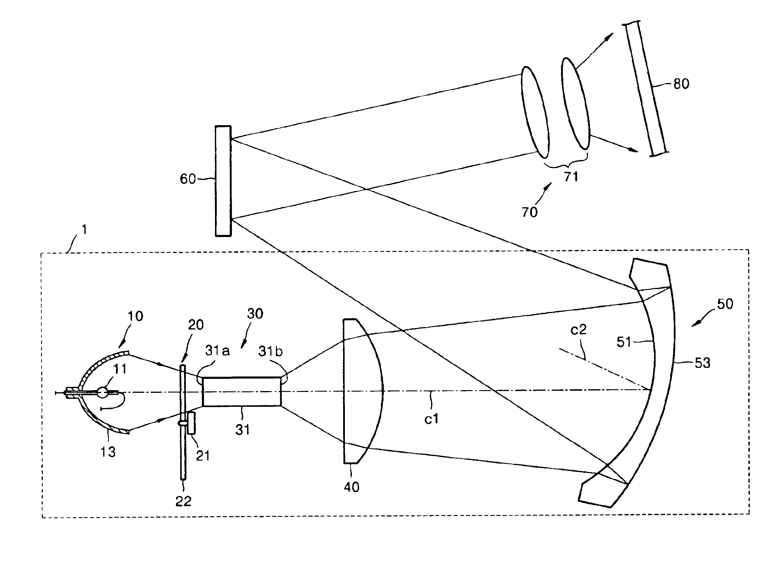
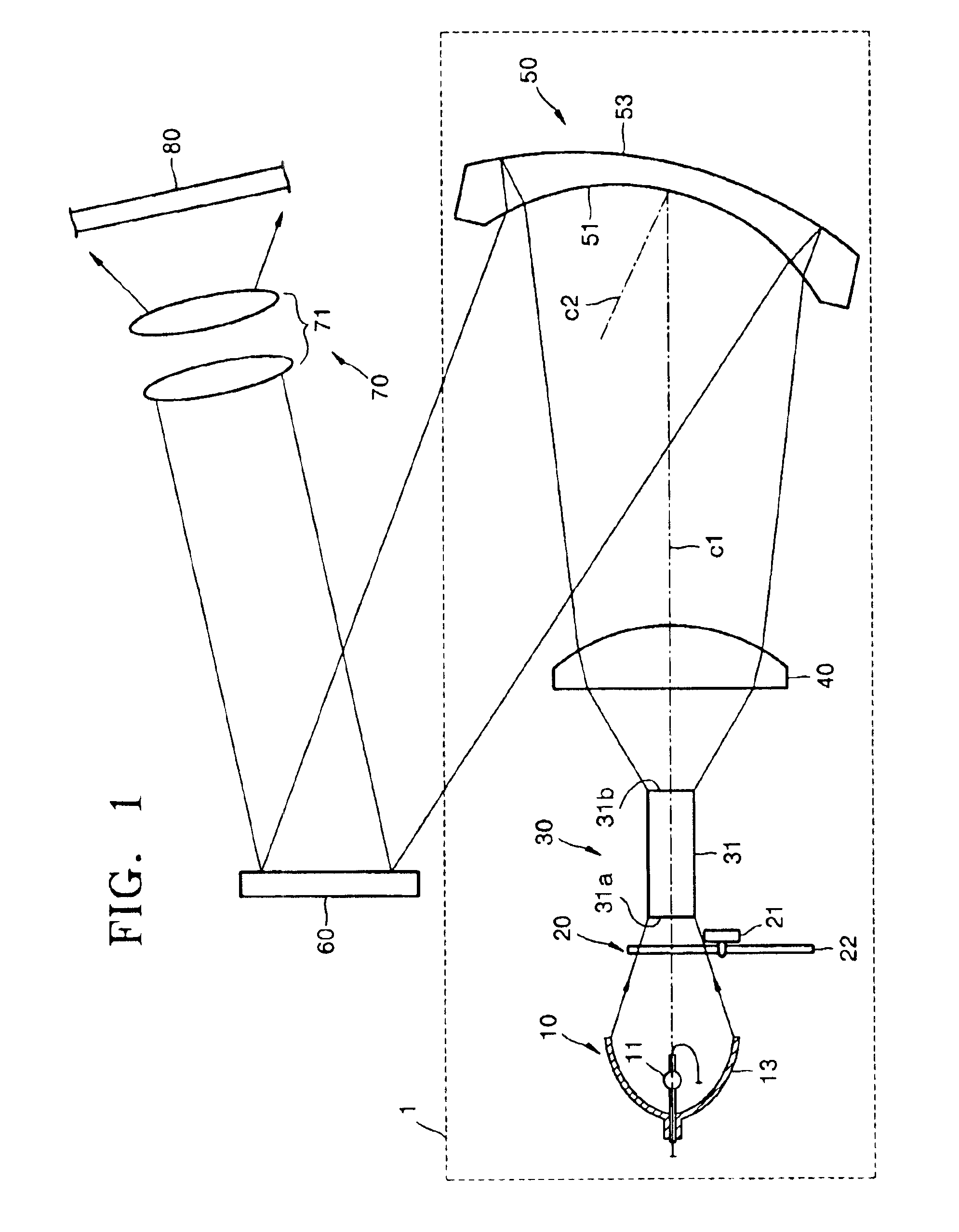
[0030]FIG. 1 shows an image projection system with an optical illumination system 1 according to an embodiment of the present invention. Referring to FIG. 1, the optical illumination system 1 includes a light source 10, at least one illuminating lens 40 and a Mangin mirror 50 that illuminate light emitted from the light source 10 onto a predetermined reflective device. In addition to the optical illumination system 1, the image projection system further includes a reflective display 60, which is the predetermined reflective device, and a projection optical system 70.

[0031]The light source 10 can be lamp type. The lamp type light source 10 includes a lamp 11 th...


PUM


Abstract

An optical illumination system and an image projection system including the same include a light source, at least one illuminating lens and a Mangin mirror that illuminate light emitted from the light source on a predetermined reflective device, the Mangin mirror including a concave refracting surface that refracts and transmits light incident from the illuminating lens, and a convex reflecting surface disposed behind the concave refracting surface to internally reflect the light refracted by the concave refracting surface back toward the concave refracting surface and tilted with respect to the illuminating lenses. The light reflected from the convex reflecting surface and then refracted through the concave refracting surface propagates along a path that is different from a path of the light emitted from the illuminating lens.

Description

CROSS-REFERENCE TO RELATED APPLICATIONS[0001]This application claims the priority of Korean Patent Application No. 2003-21621, filed on Apr. 7, 2003, in the Korean Intellectual Property Office, the disclosure of which is incorporated herein in its entirety by reference.BACKGROUND OF THE INVENTION[0002]1. Field of the Invention[0003]The present invention relates to an optical illumination system designed to emit light onto a reflective display device with micromirrors that turn light on or off by changing angles of reflection, and a projection system including the same.[0004]2. Description of the Related Art[0005]In general, an image projection system that can be applied to rear projection televisions or front projection projectors includes an optical illumination system, a display device, and a projection optical system. The display device modulates light illuminated by the optical illumination system, and the projection optical system projects the modulated light to display an enla...

Claims


Application Information

Patent Timeline
IPC IPC(8): G02B17/08F21S2/00G03B21/14F21V13/00G02B27/00G03B21/00
CPCG02B17/08G02B17/0856G02B19/0028G02B19/0047G02B19/0066G02B27/00
Inventor CHA, YONG-DOK
Owner SAMSUNG ELECTRONICS CO LTD
Why Eureka
Try Eureka