Patient positioning and transport system

Inactive Publication Date: 2005-08-16
DEUTES KREBSFORSCHUNGSZENT STIFTUNG DES OFFENTLICHEN RECHTS
View PDF14 Cites 44 Cited by
  • Summary
  • Abstract
  • Description
  • Claims
  • Application Information

AI Technical Summary

Benefits of technology

[0032]The various embodiments of the invention can be used in arbitrary combination. A larger number of adapter plates or replaceable adapter plates may be provided. With such replaceable adapter plates, the conditions of the respective hospital, i.e. the existing devices may be taken into cons

Problems solved by technology

It is therefore not possible to design a stretcher which can be removed from a cart which simultaneously satisfies all these numerous requirements.
The underlying adaptor plate may occupy a certain amount of space but must not satisfy the high requ

Method used


Image

  • Patient positioning and transport system
  • Patient positioning and transport system
  • Patient positioning and transport system

Examples


Embodiment Construction

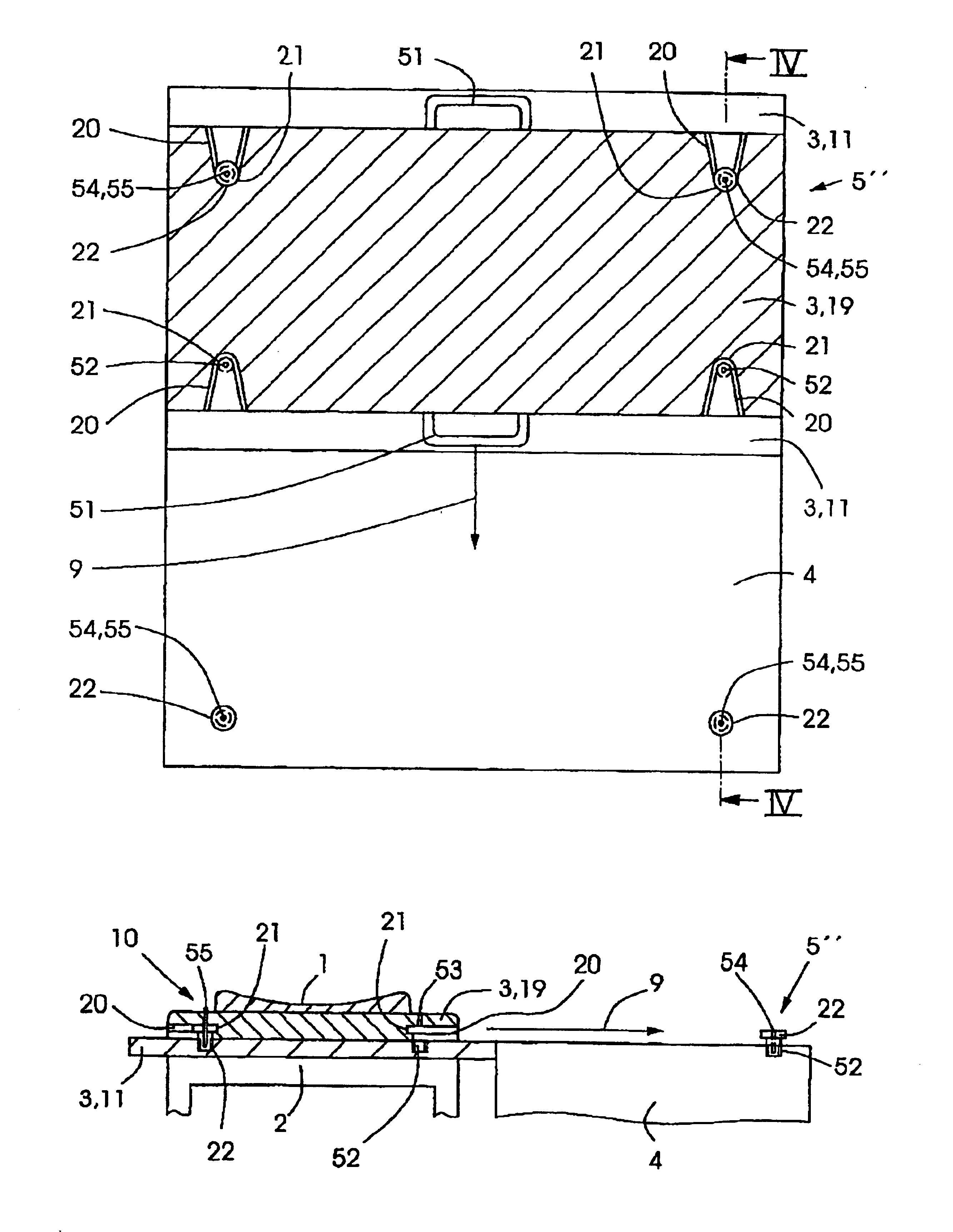
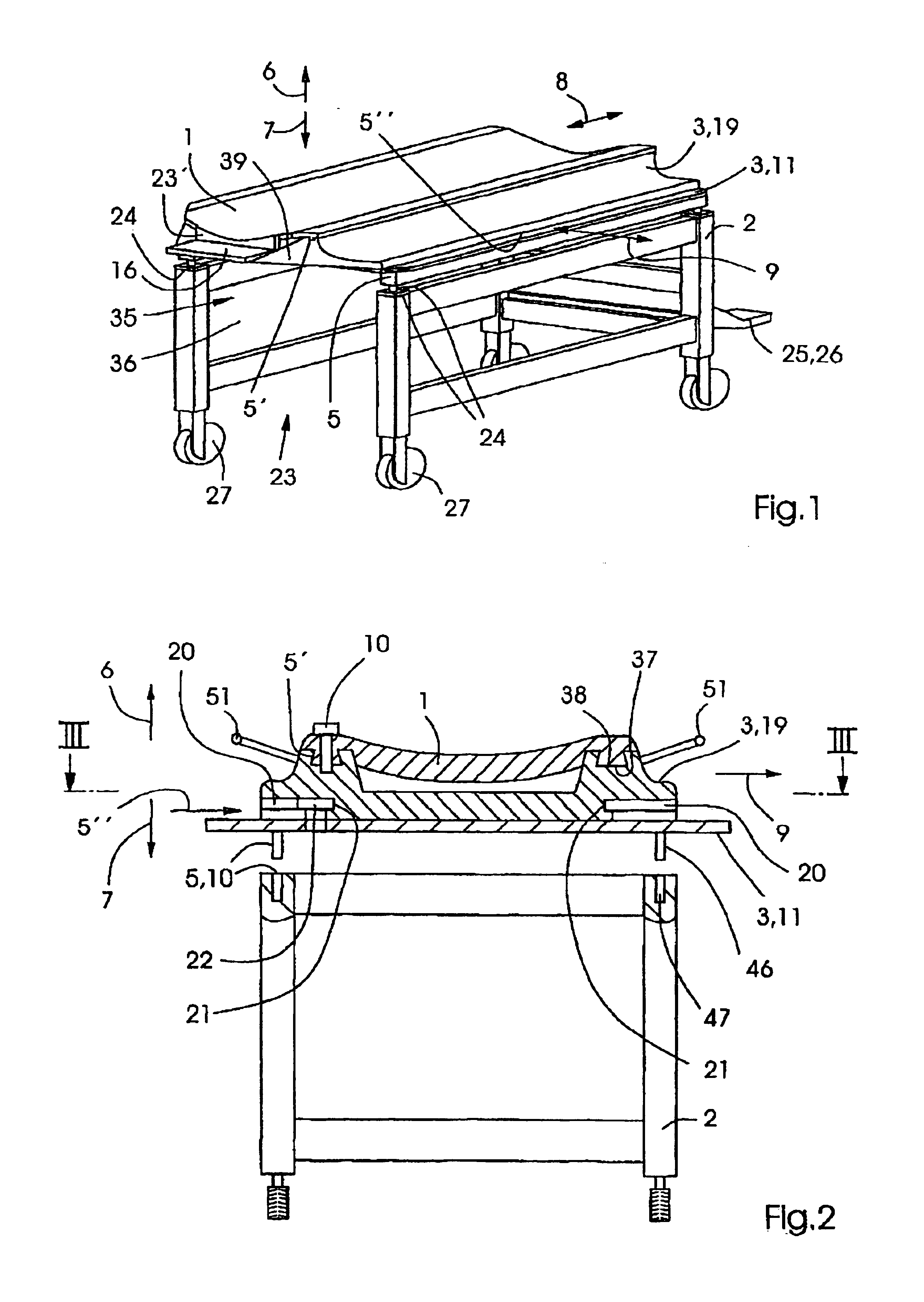
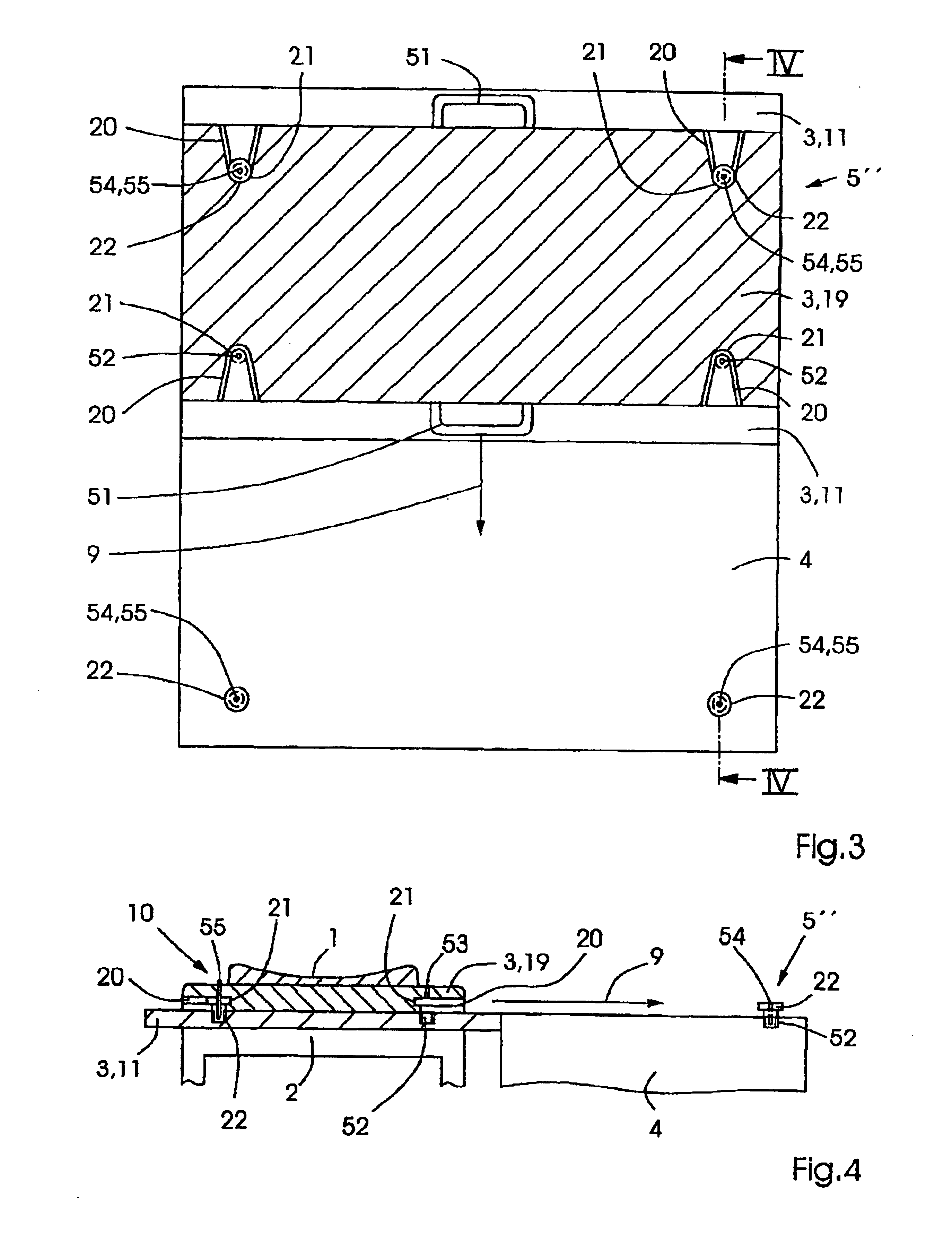
[0045]FIG. 1 shows an embodiment of the invention with a stretcher 1 disposed on a cart 2. The stretcher 1 has two associated adapter plates 3, namely a base plate 11 and an intermediate plate 19. The stretcher 1 is disposed on the intermediate plate 19 such that it can be displaced in a longitudinal direction (in the direction of arrow 8). The intermediate plate 19 is disposed on the base plate 11 to permit displacement in a transverse direction (in the direction of the arrow 9). The base plate 11 is disposed on the cart 2 in a secure fashion, wherein raising in the direction of the arrow 6 and lowering in the direction of the arrow 7 are possible. FIG. 2 shows the corresponding designs of the positioning means 5, 5′, 5″ which serve to move the stretcher 1 to different diagnosis or treatment stations 4.

[0046]FIG. 1 shows an embodiment of the cart 2 having a portal-like opening 36 at its front side 35 for movement over a diagnosis or treatment station 4 to position the stretcher 1 o...


PUM


Abstract

The invention relates to a patient positioning and transport system comprising a transportable stretcher (1) and a cart (2) for transporting the stretcher (1) with the patient. The stretcher (1) can be removed from the cart (2) to be placed on a diagnosis or treatment station (4). A patient positioning and transport system of the aforementioned type should be designed as to avoid, to the greatest possible extent, repositionings of the patient between separate diagnosis or treatment stations (4). Towards this end, at least one adapter plate (3) that can be assigned to the stretcher (1) is provided, whereby the stretcher (1), the adapter plate (3) and the cart (2) can be joined to another and are configured in such a manner that the stretcher (1) with the patient can be transferred from the cart (2) to various, differently designed diagnosis or treatment stations (4) and back.

Description

[0001]This application is the national stage of PCT / EP02 / 05129 filed on May 10, 2002 and claims Paris Convention priority of DE 101 27 210.3 filed Jun. 5, 2001.BACKGROUND OF THE INVENTION[0002]The invention concerns a patient positioning and transport system with a transportable stretcher and a cart for transporting the stretcher along with the patient, wherein the stretcher can be removed from the cart and be disposed on a diagnosis or treatment station.[0003]The underlying problem of the invention concerns the fact that different diagnosis or treatment stations each have their own stretchers. Patients who must be diagnosed and treated sequentially at several stations must be positioned onto the stretchers of those stations and back onto the transport cart. Conventional carts may have stretchers which can be removed from the cart and placed onto an operation table. This however, does not solve the problems involved when different diagnosis or treatment stations of different constru...

Claims


Application Information

Patent Timeline
IPC IPC(8): A61B6/04
CPCA61B6/0407A61B6/0442
Inventor PASTYR, OTTOECHNER, GERNOTSCHLEGEI, WOLFGANGSTURM, VOLKERTREUER, HARALD
Owner DEUTES KREBSFORSCHUNGSZENT STIFTUNG DES OFFENTLICHEN RECHTS
Why Eureka
Try Eureka