Venturi system using closed loop air return for conveying flexible fabrics

a closed-loop air return and flexible fabric technology, applied in bulk conveyors, transportation and packaging, thin material processing, etc., can solve the problems of increasing the capital cost of laundry equipment, not being satisfactory in all respects, and not being able to meet the needs of all of these manual operations, so as to reduce equipment costs, labor costs and space requirements

Inactive Publication Date: 2005-09-13
AUTOMATION DYNAMICS
View PDF16 Cites 29 Cited by
  • Summary
  • Abstract
  • Description
  • Claims
  • Application Information

AI Technical Summary

Benefits of technology

[0007]The present invention is directed to a method and apparatus for conveying flexible fabric articles in an improved way that avoids the shortcomings of vacuum bin systems. In particular, the present invention provides a venturi system that dramatically reduces the equipment costs, labor costs and space requirements compared to vacuum bin systems, belt conveyors and scales.
[0008]In accordance with the invention, a uniquely arranged venturi structure is provided for applying a suction force at a selected location along the conveyor tube system rather than at its discharge end as is necessary with a vacuum bin system. Because the venturi is located along the conveyor tubing, the tubing can discharge the fabric items directly into sling carts or other receptacles while also calculating the combined weight of the sling cart contents, thus eliminating the space occupied by the vacuum bins and the intermediate conveying system as well as the labor that is required to manually unload the articles from the vacuum bins and to later load them into the sling carts. This eliminates the need to manually weigh each sling.
[0010]An important feature of the invention is the provision of a vent in the conveyor tubing at a location downstream from the venturi. The vent is preferably a screened gap in the tubing which allows a portion of the air to escape. The vent significantly enhances the smoothness and reliability of the conveyor system by partially relieving the air pressure and thereby suppressing pressure fluctuations and other unfavorable pressure conditions that can adversely affect operation of the conveyor system. An adjustable sleeve in the preferred embodiment of the invention allows the width of the gap to be adjusted as necessary.
[0011]The invention is further characterized by a closed-loop return system that returns air from the vent to the suction side of the blower. The return system provides numerous advantages, including an increase in the blower suction, a decrease in the pressure on the discharge side of the blower to more effectively convey fabrics through the main conduit, and a reduction in noise.

Problems solved by technology

Although vacuum bins of this type have achieved considerable popularity, they have not been satisfactory in all respects.
Their relatively high cost adds appreciably to the capital costs of the laundry equipment.
As can easily be appreciated, the need for all of these manual operations adds significantly to the overall labor costs.
Finally, the vacuum bins and conveyors that transport articles from the bins to the sling carts occupy considerable space.
This is particularly unsatisfactory in the case of commercial laundries because they are usually located in high cost urban areas where they are close to their major customers.

Method used


Image

  • Venturi system using closed loop air return for conveying flexible fabrics
  • Venturi system using closed loop air return for conveying flexible fabrics
  • Venturi system using closed loop air return for conveying flexible fabrics

Examples


Embodiment Construction

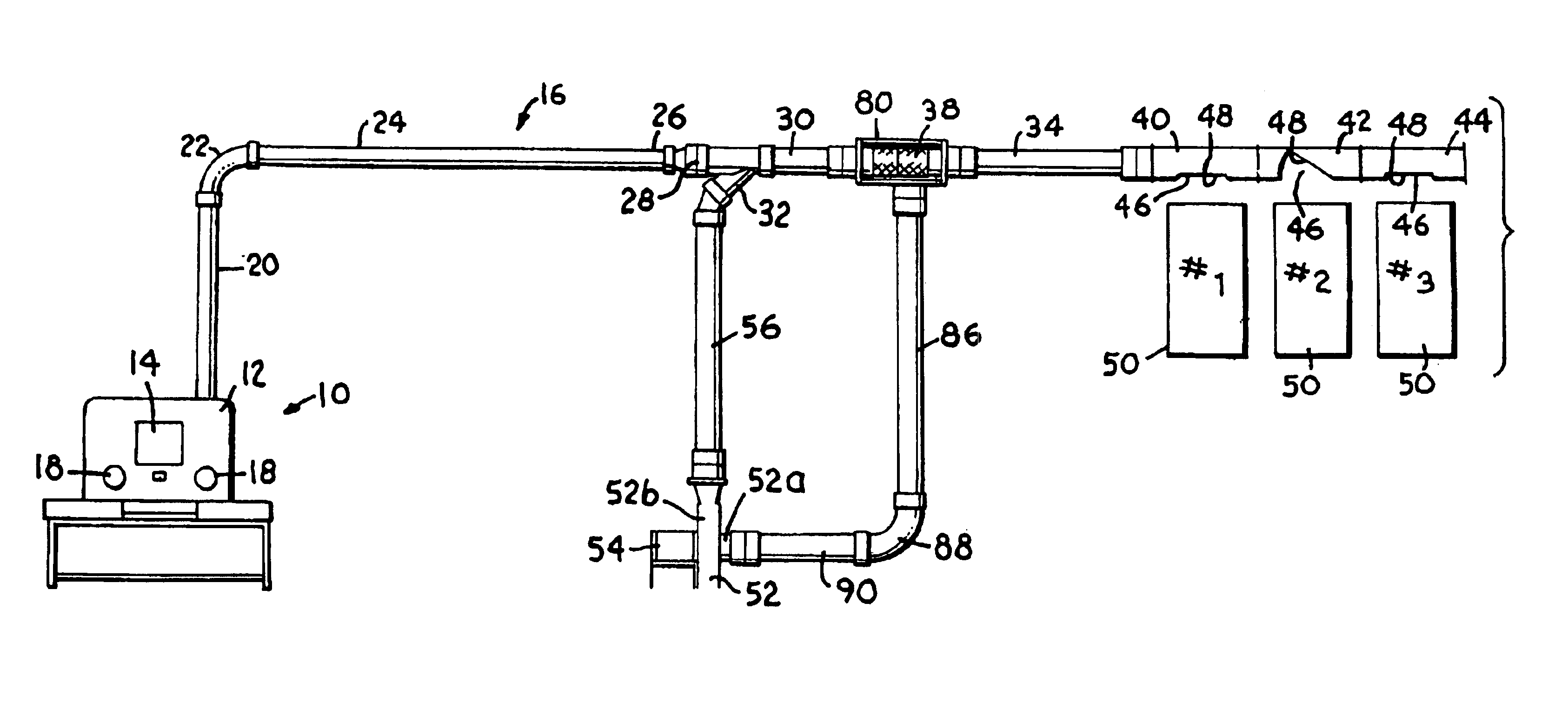
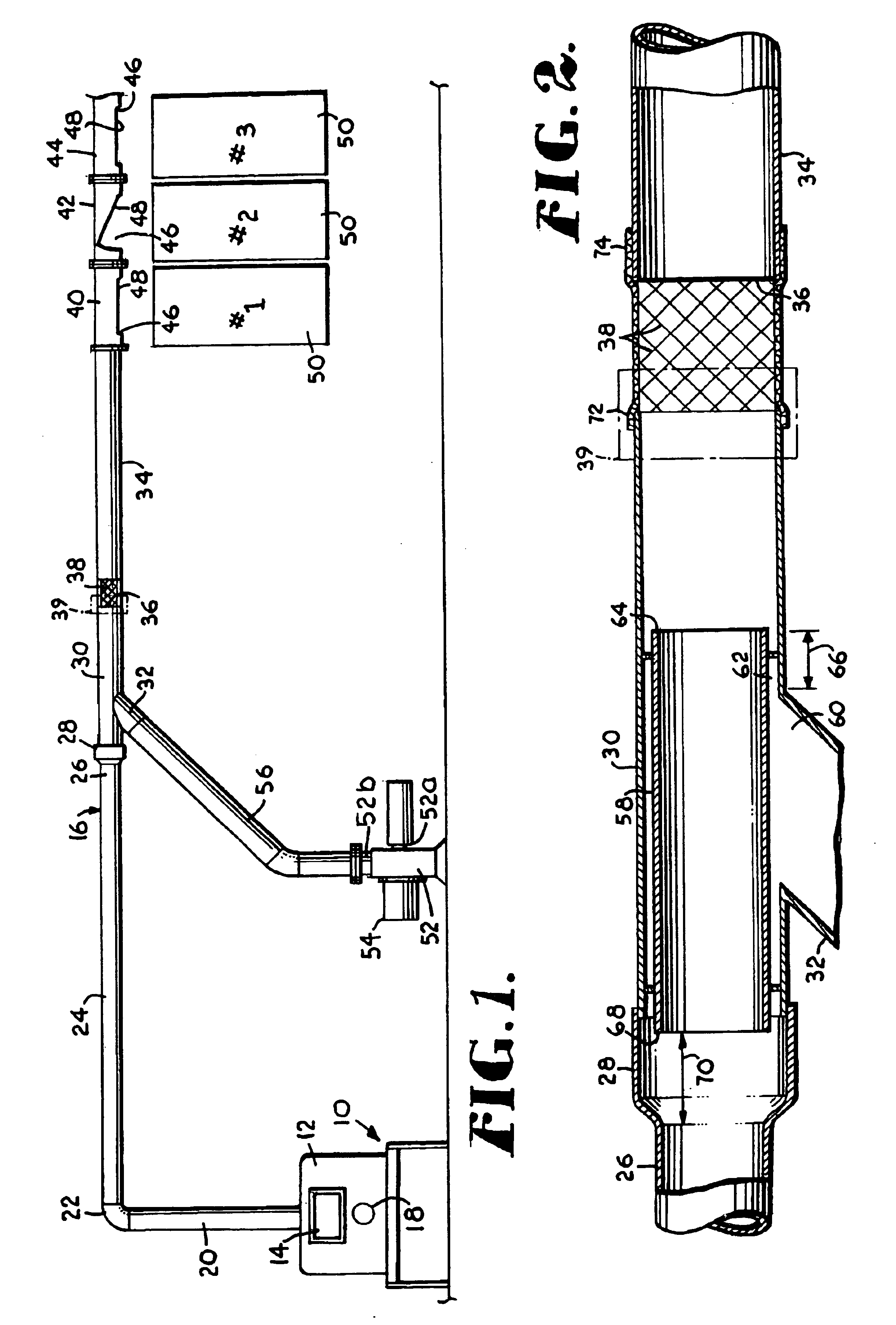
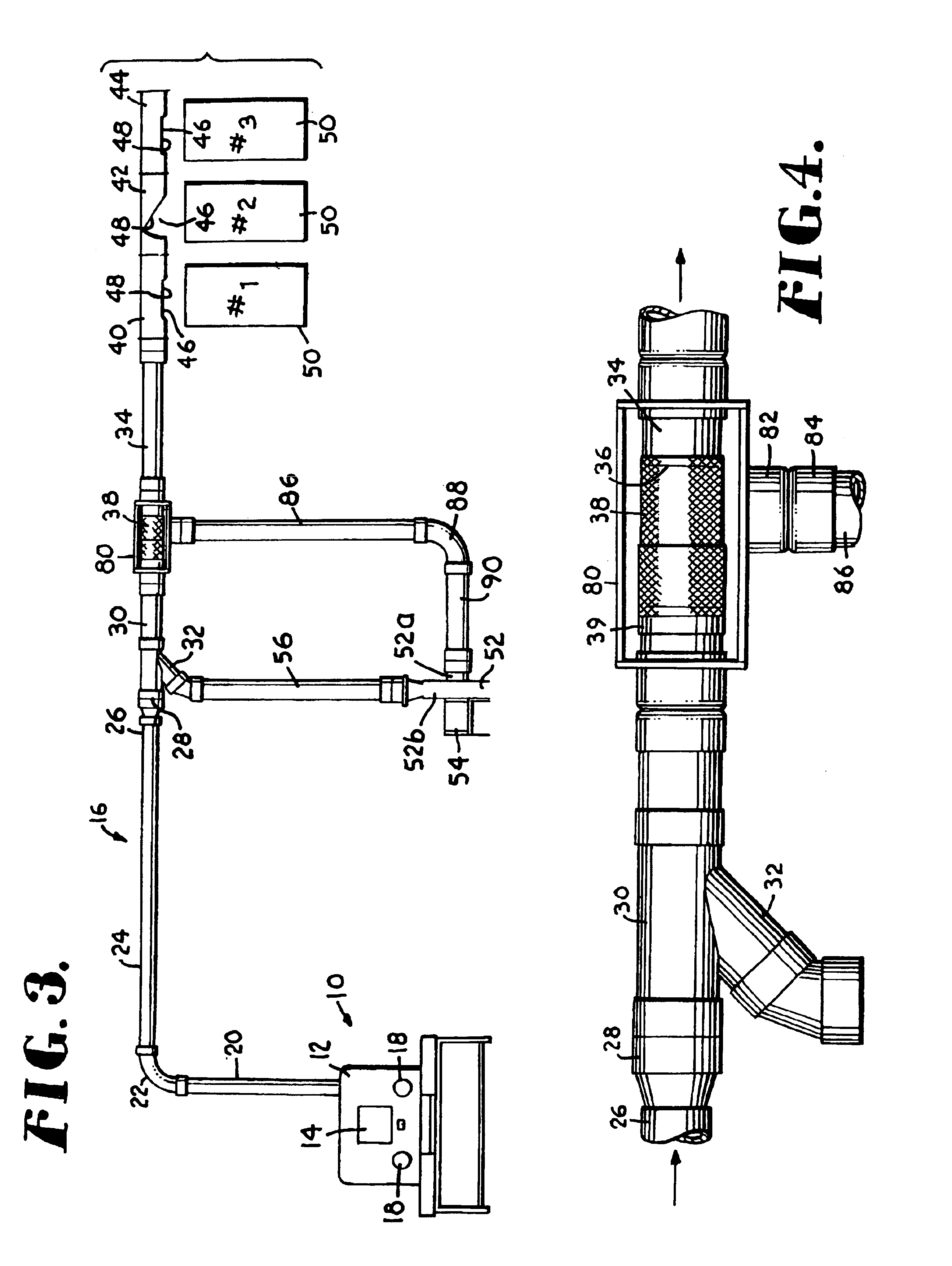
[0018]The present invention is directed to a method and apparatus for the pneumatic conveying of fabric materials such as table linens (table cloths, napkins and the like), uniforms, and other articles that are typically laundered in commercial laundries, as well as other flexible fabrics that are pneumatically conveyed in other applications. FIG. 1 illustrates diagrammatically a pneumatic conveying system of the type that may be installed in a commercial laundry facility. A sorting table generally identified by numeral 10 or a similar sorting station is used for the sorting of articles and may be equipped with a back panel 12 having an operator interface panel 14. Pneumatic conveyor tubing generally identified by numeral 16 extends from the back of the table and is located for the most part at an overhead location, although other locations are possible.

[0019]An opening 18 in the panel 12 may provide an input opening into which articles may be fed into a vertical tube 20 which is pa...


PUM


Abstract

A venturi incorporated in a pneumatic tube conveying system for flexible textile fabrics such as uniforms and table linens handled in commercial laundries. The venturi includes an angled pipe which joins the main piping system at an acute angle and which receives air from a blower. An inside pipe is installed within the main piping to create a restriction at the connection of the venturi with the main piping. The restriction and angled connection of the venturi pipe creates a low pressure area which draws fabric articles through the piping and discharges them directly into receptacles such as sling carts. A screened vent in the piping downstream from the venturi allows the escape of air to enhance the reliability and efficiency of the pneumatic conveying system. The exposure of the vent can be adjusted by a sleeve that slides back and forth on the conveyor tube at the location of the vent. A closed-loop return air system extends from the vent to the suction side of the blower to reduce the noise level and provide more advantageous pressure conditions in the conveying system.

Description

CROSS-REFERENCE TO RELATED APPLICATIONS[0001]This application is a divisional of application Ser. No. 10 / 662,147, filed on Sep. 12, 2003 now U.S. Pat. No. 6,789,715, which is a continuation-in-part of application Ser. No. 09 / 892,929, filed on Jun. 27, 2001, now U.S. Pat. No. 6,619,525, issued Sep. 16, 2003, in the names of Michael S. Frankeberger and Steven D. Twombly.STATEMENT REGARDING FEDERALLY SPONSORED RESEARCH OR DEVELOPMENT[0002]Not applicableTECHNICAL FIELD[0003]This invention relates generally to the pneumatic conveying of flexible fabrics such as uniforms, table linens and other articles handled by commercial laundries and industrial uniform processing plants, as well as other fabric items that are conveyed between different locations in other types of applications. More particularly, the invention is directed to a method and apparatus that makes use of a venturi to provide a suction force for pulling fabrics through conveyor tubes and a closed loop return conduit providin...

Claims


Application Information

Patent Timeline
Patent Type & Authority Patents(United States)
IPC IPC(8): B65G51/00B65G51/02D06B3/30
CPCB65G51/02
Inventor FRANKEBERGER, MICHAEL S.TWOMBLY, STEVEN D.
Owner AUTOMATION DYNAMICS
Why Eureka
Try Eureka