Linear oscillator

a linear oscillator and oscillator technology, applied in the field of linear oscillators, can solve the problems of high vibration and achieve the effect of small noise and low vibration

Inactive Publication Date: 2005-10-25
HEWLETT PACKARD DEV CO LP
View PDF16 Cites 47 Cited by
  • Summary
  • Abstract
  • Description
  • Claims
  • Application Information

AI Technical Summary

Benefits of technology

[0008]In view of the above, it is an object of the invention to provide a linear oscillator that gives a low vibration and small noise and can be miniaturized.
[0025]An aspect of the present invention is the linear oscillator further in which the yoke or the moving part is provided with an eddy current loss reducing means for reducing an eddy current loss.

Problems solved by technology

In this case, however, there would rise various problems due to a mechanical loss or noise occurring at the motion direction converting mechanism and a difficulty in miniaturization.
Besides the above, there has been known such a linear oscillator that uses no motion direction converting mechanism to reciprocate the moving part to axially by use of an electromagnetic force as well as by use of a resonance frequency determined by a spring force of a spring member having the moving part as a spring oscillation system and a mass of the moving part, however this causes high vibration because of inertia force of the moving part.

Method used


Image

  • Linear oscillator
  • Linear oscillator
  • Linear oscillator

Examples


Embodiment Construction

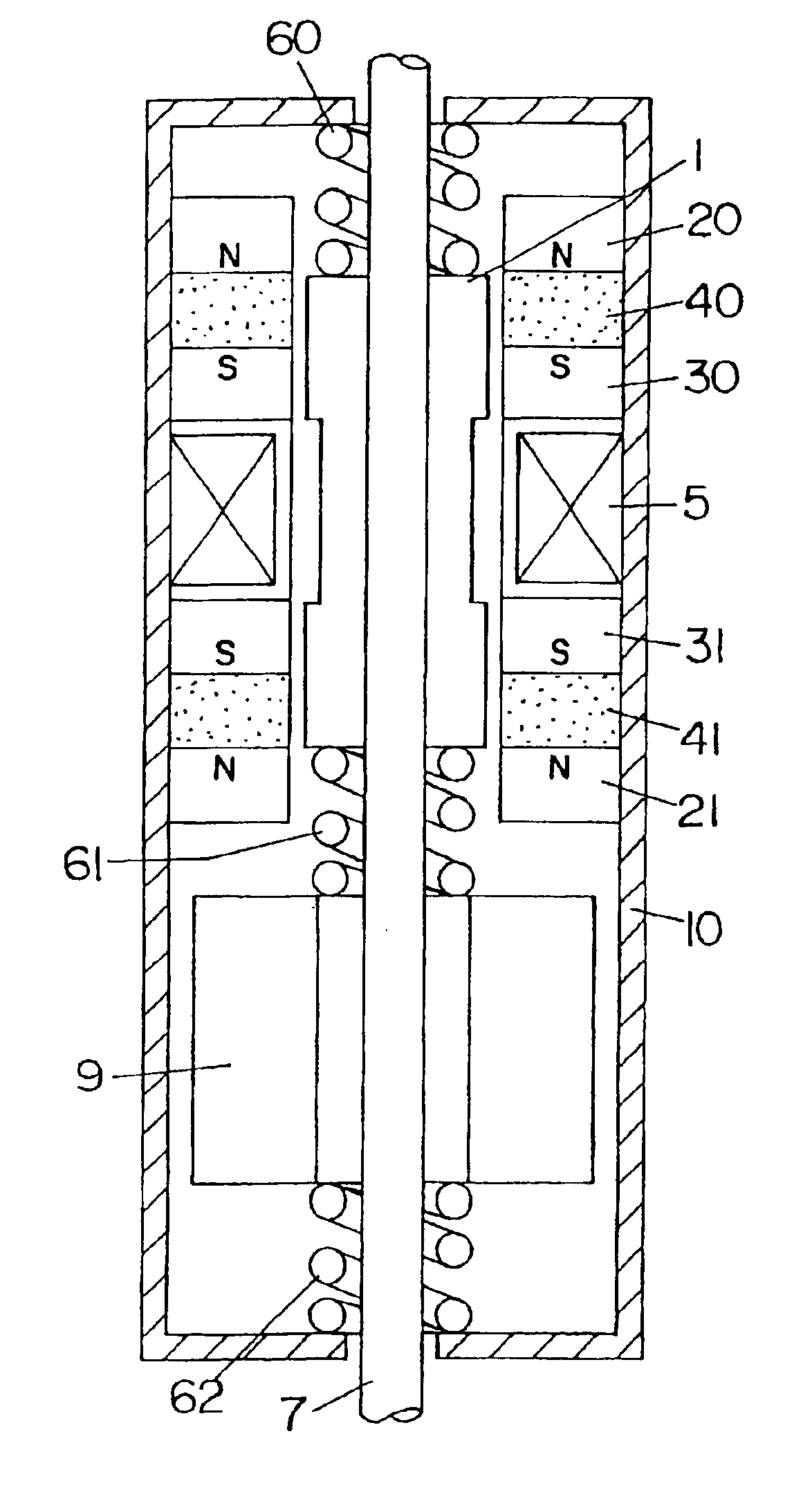
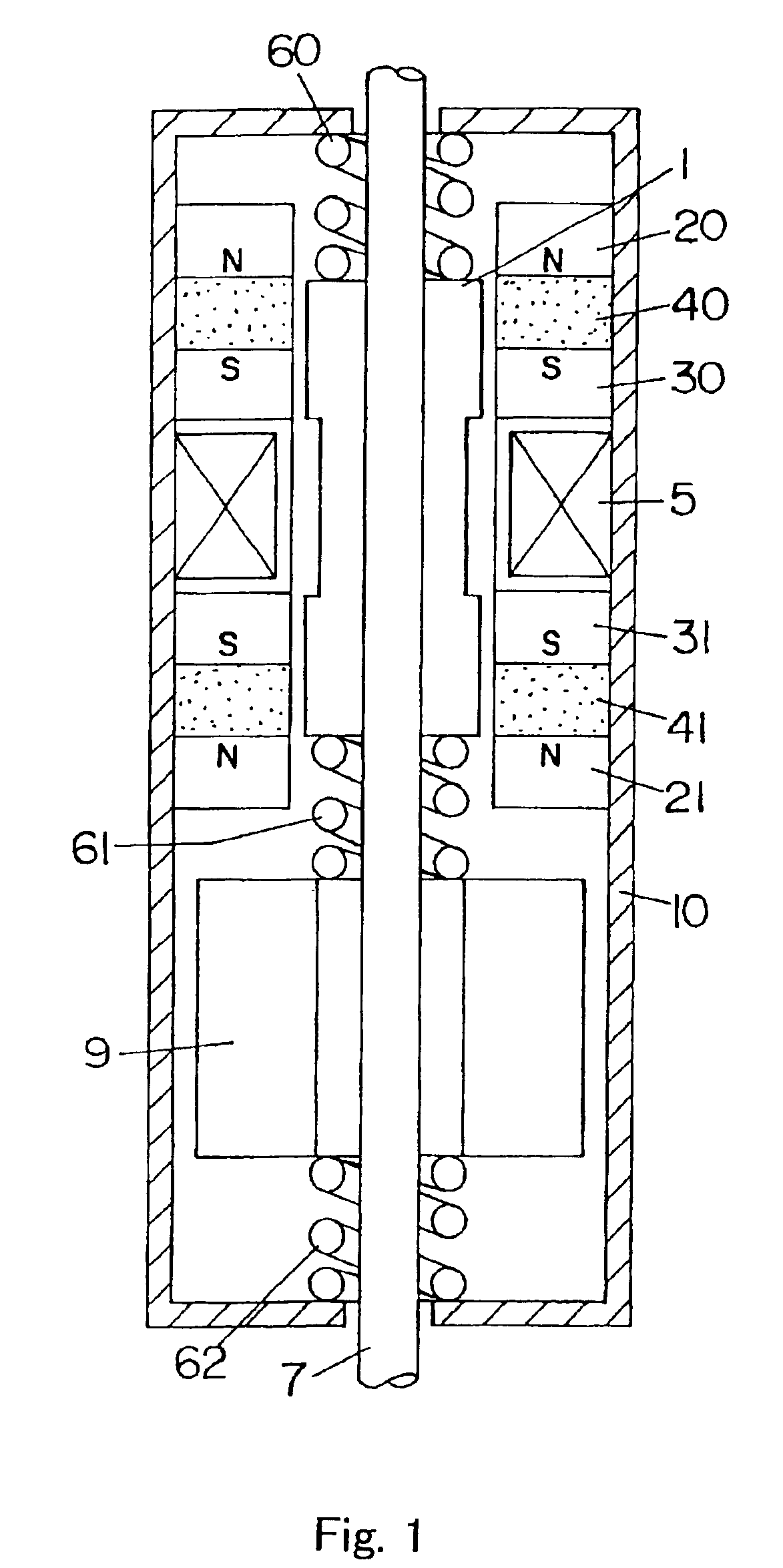
[0053]FIG. 1 shows one embodiment of the invention, in which a cylindrical plunger 1 made of a magnetic substance such as iron constituting the moving part housed in the case has a large diameter at its both ends and a small diameter at its center in such a configuration that through the plunger 1, an output-take-out shaft 7 is pierced and fixed therein as a connection element and on the periphery of the plunger 1 is provided a coil 5. At both axial ends of the above-mentioned annular coil 5 fixed on the inner surface of a shield case 10 acting as the case are provided annular permanent magnets 40 and 41 magnetized symmetrically with respect to the coil 5, so that between the magnets 40 and 41 and the coil 5 are provided annular second yokes 30 and 31, and on the sides of the magnets 40 and 41 opposite to the yokes 30 and 31 are provided annular first yokes 20 and 21 respectively. Those coil 5, permanent magnets 40 and 41, and yokes 30, 31, 20, and 21 are combined to make up an elec...


PUM


Abstract

A linear oscillator includes a reciprocating moving part, a case to contain the moving part, and an amplitude control spindle moveably supported in the case. The moving part and the amplitude control spindle reciprocate at a frequency approximately equal to the resonance frequency of the linear oscillator.

Description

[0001]This application is a Division of application Ser. No. 09 / 881,693, filed on Jun. 18, 2001, the contents of which are herein incorporated by reference.BACKGROUND OF THE INVENTION[0002]1. Field of the Invention[0003]The invention relates to a linear oscillator in which a moving part thereof reciprocates.[0004]2. Description of the Related Art[0005]There has been employed such a linear oscillator using a motion direction converting mechanism to convert a motor revolutionary motion into a reciprocating linear motion that can be used in a driving part for use in mechanical control or of an electric razor or a power tooth brush.[0006]In this case, however, there would rise various problems due to a mechanical loss or noise occurring at the motion direction converting mechanism and a difficulty in miniaturization.[0007]Besides the above, there has been known such a linear oscillator that uses no motion direction converting mechanism to reciprocate the moving part to axially by use of...

Claims


Application Information

Patent Timeline
Patent Type & Authority Patents(United States)
IPC IPC(8): A61C17/34A61C17/16B26B19/00B26B19/28H02K33/00H02K33/16H02K41/02
CPCA61C17/34A61C17/3445B26B19/282H02K33/16H02K41/02
Inventor ICHII, YOSHITAKAHIRATA, KATSUHIROARIKAWA, YASUSHIYAMADA, TOMIOYABUUCHI, HIDEKAZUINOUE, HIROKI
Owner HEWLETT PACKARD DEV CO LP
Why Eureka
Try Eureka