Pipette tip, pipetting device and combination consisting of a pipette tip and pipetting device

a technology of pipetting device and pipette tip, which is applied in the direction of measuring device, burette/pipette, sampling, etc., can solve the problems of inability to define the position of the pipette tip relative to the coupling stud, inability to apply high forces, and inability to form micro-fissures in the pipette tip, etc., to achieve the effect of increasing the lifetime of the sealing elemen

a technology of pipetting device and pipette tip, which is applied in the direction of measuring device, burette/pipette, sampling, etc., can solve the problems of inability to define the position of the pipette tip relative to the coupling stud, inability to apply high forces, and inability to form micro-fissures in the pipette tip, etc., to achieve the effect of increasing the lifetime of the sealing elemen

US7033543B1Inactive Publication Date: 2006-04-25HAMILTON BONADUZ AG

Image

  • Pipette tip, pipetting device and combination consisting of a pipette tip and pipetting device
  • Pipette tip, pipetting device and combination consisting of a pipette tip and pipetting device
  • Pipette tip, pipetting device and combination consisting of a pipette tip and pipetting device

Examples


Embodiment Construction

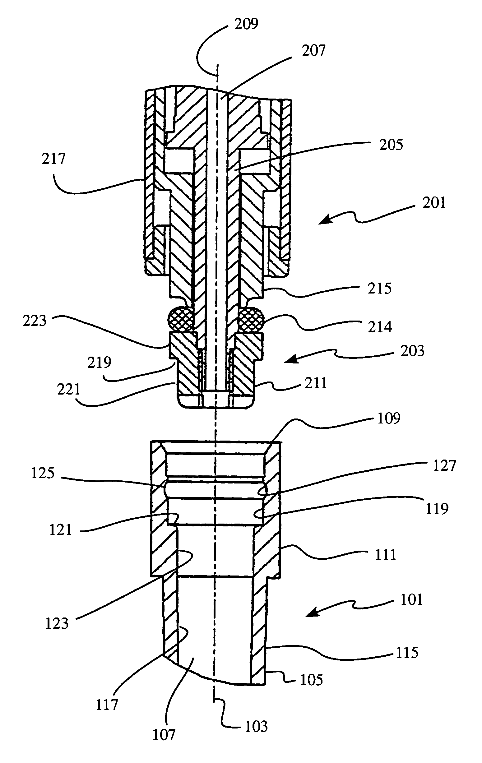
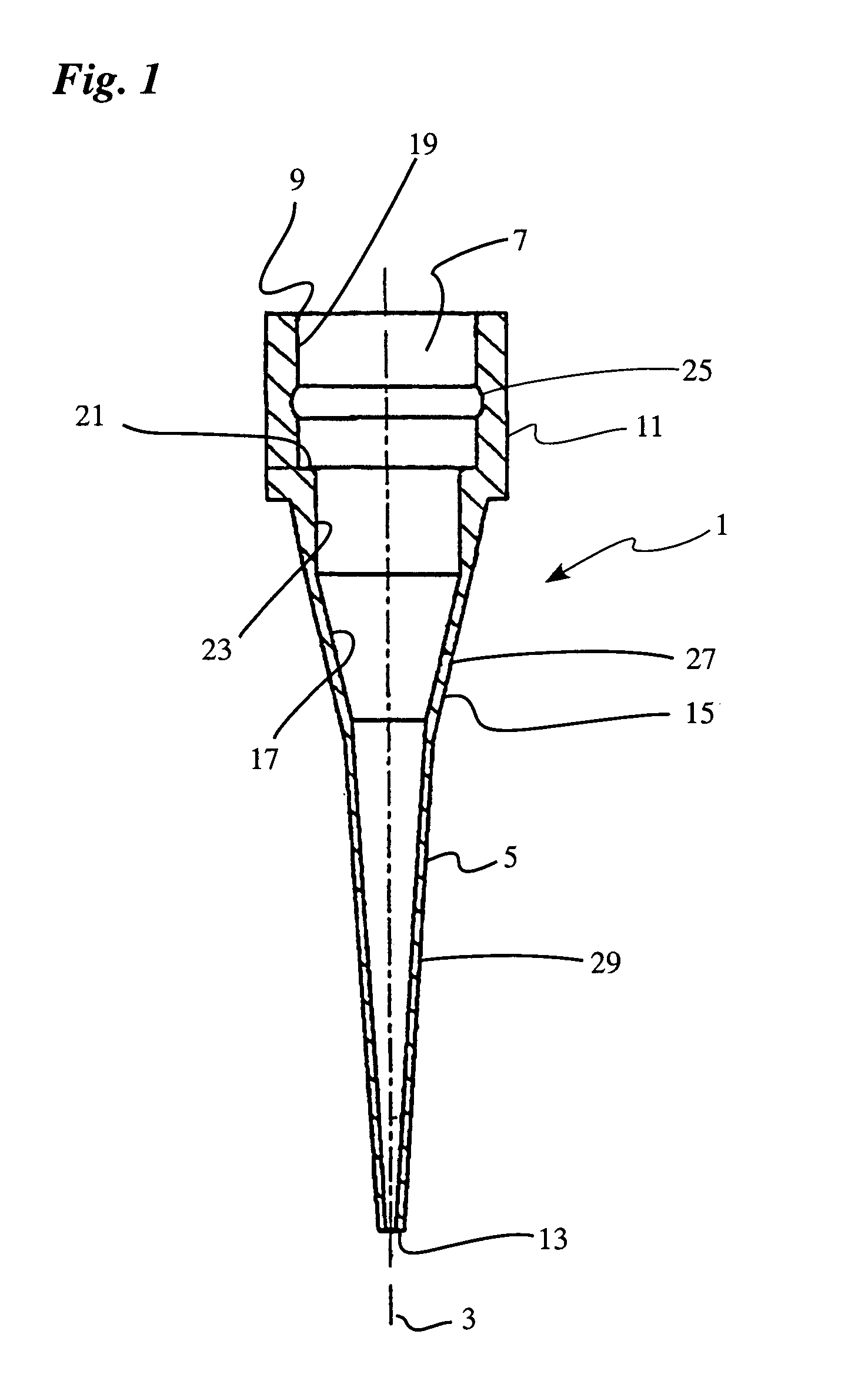
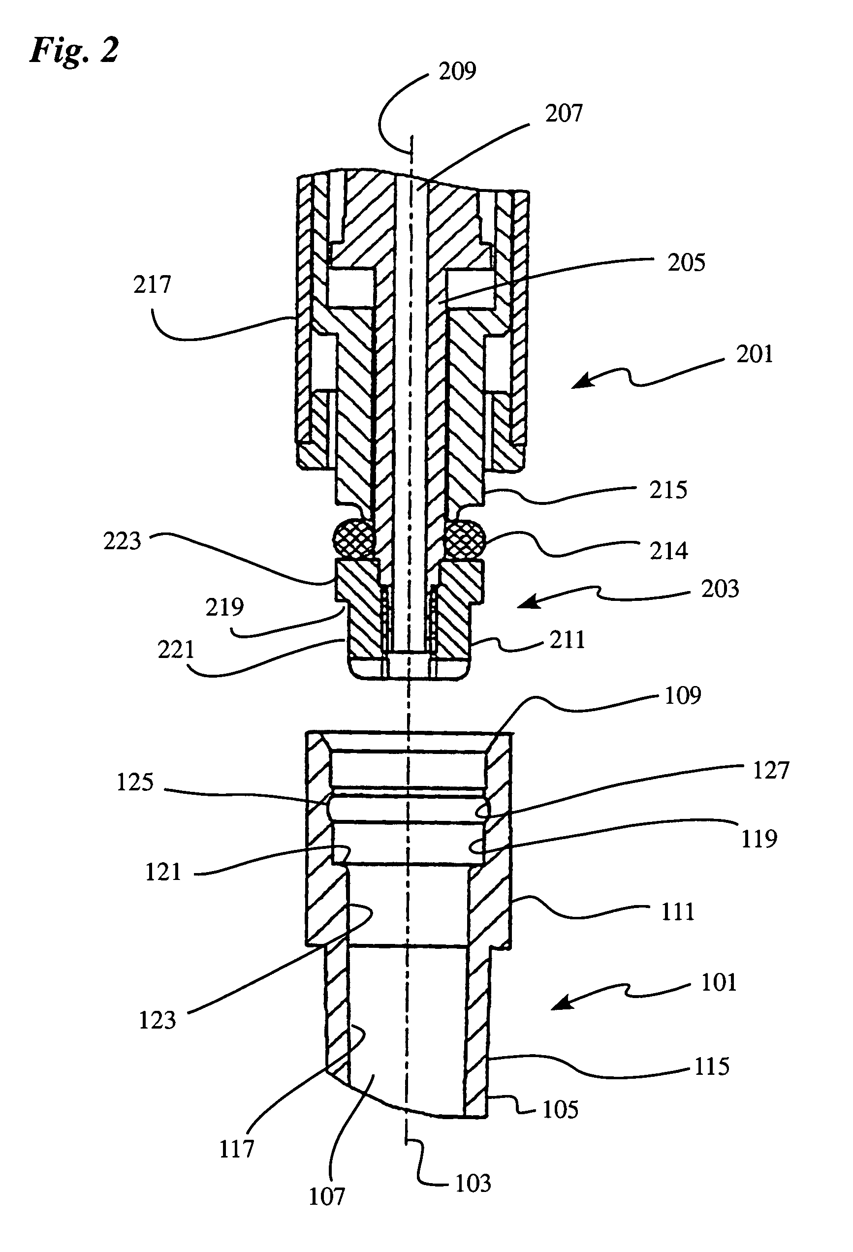
[0025]Reference is made to FIG. 1 first. There one can see a pipette tip 1 which is also designated as a tip, with a jacket 5 which is rotationally symmetric around a longitudinal axis 3 and encloses a passage opening 7 which axially passes through the pipette tip 1. As seen in FIG. 1, in the area of its upper, open front end 9, the pipette tip 1 has a coupling area 11 used for coupling to a pipette device that is not depicted in FIG. 1. Opposite the front end 9, the pipette tip 1 has a mouth end 13, which is intended for immersion in the medium to be pipetted.

[0026]The jacket 5 of the pipette tip 1 has an outside circumference 15 and an inside circumference 17. In the coupling area 11 the inside circumference 17 has a cylindrical inside circumference section 19, which essentially extends from the front end 9 to an annular stepped shoulder 21, followed by another cylindrical inside circumference section 23. The stepped shoulder 21 forms an axially directed stop surface. An annular g...


PUM


Abstract

A pipette device has a coupling stud on which a pipette tip can be stuck in a slipping-on direction for coupling. The coupling stud has an adjustable pre-stress member that can be adjusted into a prestress state and a release state via an actuation device which is provided in the coupling stud. The pipette tip has an axial stop which interacts with a counter-stop of the coupling stud in an axial coupling position of the pipette tip. The prestress member in its prestress state acts upon a working surface of the stuck-on pipette tip having a surface component of the pipette tip, which extends radially inward, turned away from the stuck on direction, in such a way that it abuts sealingly on the working surface, and prestresses the pipette tip on the pipette unit into the axial coupling position. The prestress member, in its releasing state, substantially releases the working surface of the pipette tip (101).

Description

TECHNICAL FIELD[0001]The invention concerns the placement of a pipette tip on a pipette device.BACKGROUND OF THE INVENTION[0002]Pipette devices are used, for example, in the area of molecular biology or medicinal analysis for the transfer of liquids. Special pipette tips are thereby often used which are placed on the pipette device and are intended for one-time use. Such disposable tips are also known by the designation β€œtip.” The pipette device may be a manual pipette device which merely has one single pipette unit. In the course of progressive automation, which is making its entrance into modern analysis laboratories, automated pipettes or so-called pipette robots having a large number of pipette units arranged in a row or in a matrix are also often used. With such automated pipettes, it is possible to suction samples simultaneously from a large number of vessels and to release them elsewhere.[0003]The pipette tips have been constructed, up to now, mostly with a jacket area, which...

Claims


Application Information

Patent Timeline
25 Apr 2006
Publication
US7033543B1
IPC
B01L3/02; G01N1/00; G01N1/14; G01N1/22; G01N35/10
CPC
B01L3/0279
Inventors
PANZER, ARMIN; CAMENISCH, JOHANN L.