Image display control system and method allowing connection of various kinds of image displays to one supply source

a control system and image display technology, applied in the direction of television systems, signal generators with optical-mechanical scanning, selective content distribution, etc., can solve the problems that the image display and terminal used in this situation cannot take full advantage of the advantages or improvements of each piece of equipment, and cannot adapt to the state of image display. , to achieve the effect of reliably recognizing the adjustment state of the image display and easy transmission of video signals

Inactive Publication Date: 2006-06-06
CANON KK
View PDF34 Cites 32 Cited by
  • Summary
  • Abstract
  • Description
  • Claims
  • Application Information

AI Technical Summary

Benefits of technology

[0012]It is another object of the present invention to provide easy adjustment of an image display from the supply source connected thereto.
[0013]It is still another object of the present invention to allow for easy changes of the specifications and version of the control program of the image display.
[0027]With this arrangement, the supply source can transmit a video signal in accordance with the characteristics of a connected image display. Hence, the supply source can easily transmit a video signal in accordance with even changed characteristics of the connected image display.
[0028]At the start of operation, the supply source can reliably recognize the adjustment state of the image display. Any error caused by a shift in adjustment result can be prevented prior to operation.
[0032]With this arrangement, a program specification concerning display control of the image display can be updated prior to display control, and a desired display quality can be easily obtained. The processing version of the image display can also be upgraded.

Problems solved by technology

This inevitably makes the main body large in depth, resulting in a bulky housing.
Inconveniently, the television quality or the like can only be adjusted from either the terminal or image display.
The image display and terminal used in this situation cannot take full advantage of the advantages or improvements in each piece of equipment.
This problem also arises when the image display is to be exchanged with one from a different manufacturer, or of a different size, or having a different display method.

Method used


Image

  • Image display control system and method allowing connection of various kinds of image displays to one supply source
  • Image display control system and method allowing connection of various kinds of image displays to one supply source
  • Image display control system and method allowing connection of various kinds of image displays to one supply source

Examples


first embodiment

Modification of First Embodiment

[0223]In the above-described first embodiment, video data, acoustic data (audio data), and command data are multiplexed such that acoustic data is multiplexed between video data enable timing by each HSYNC signal, and command data is multiplexed between HSYNC signals outside the video data enable period between VSYNC signals, as shown in FIGS. 17 and 18.

[0224]However, the present invention is not limited to this multiplexing timing. For example, audio data is communicated not divisionally at respective HSYNC timing but at once every VSYNC timing.

[0225]FIG. 23 shows communication timing between the terminal 2 and image display 1 when audio data is communicated not divisionally at respective HSYNC timing but at once every VSYNC timing.

[0226]In the example shown in FIG. 23, audio data is communicated at once at inter-HSYNC timing between video data enable timing upon arrival of a VSYNC signal.

[0227]This communication timing is effective when the image di...

second embodiment

[0234]In the first embodiment, the terminal 2 is connected to one image display 1, and the image display 1 is not connected to any other device. However, the present invention is not limited to this. Another optional device may be connected to one terminal or image display. For example, a video printer is connected to hard-copy image data displayed on the image display. Note that the second embodiment is the same as the first embodiment except for the following arrangement, and a detailed description thereof will be omitted.

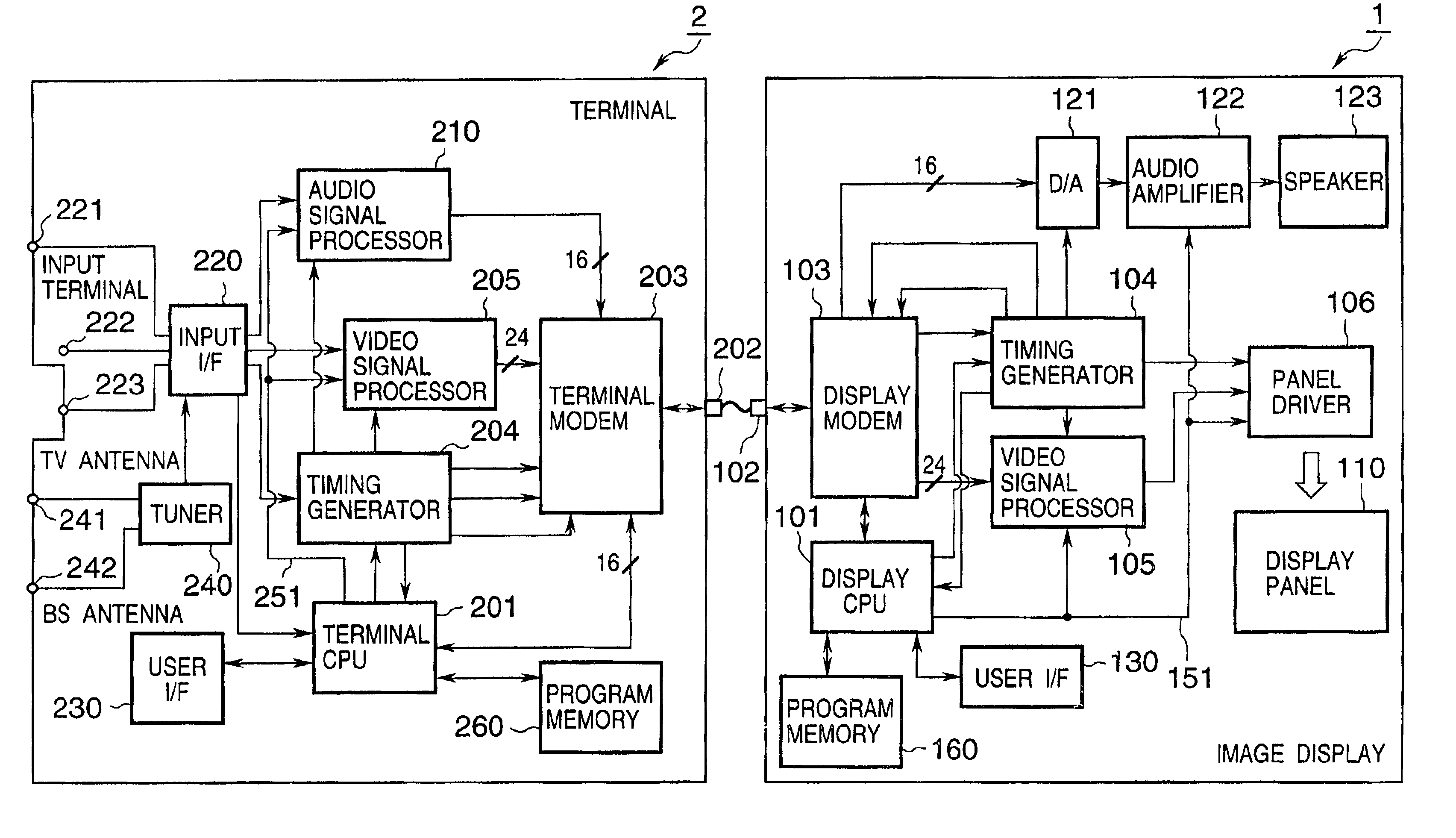
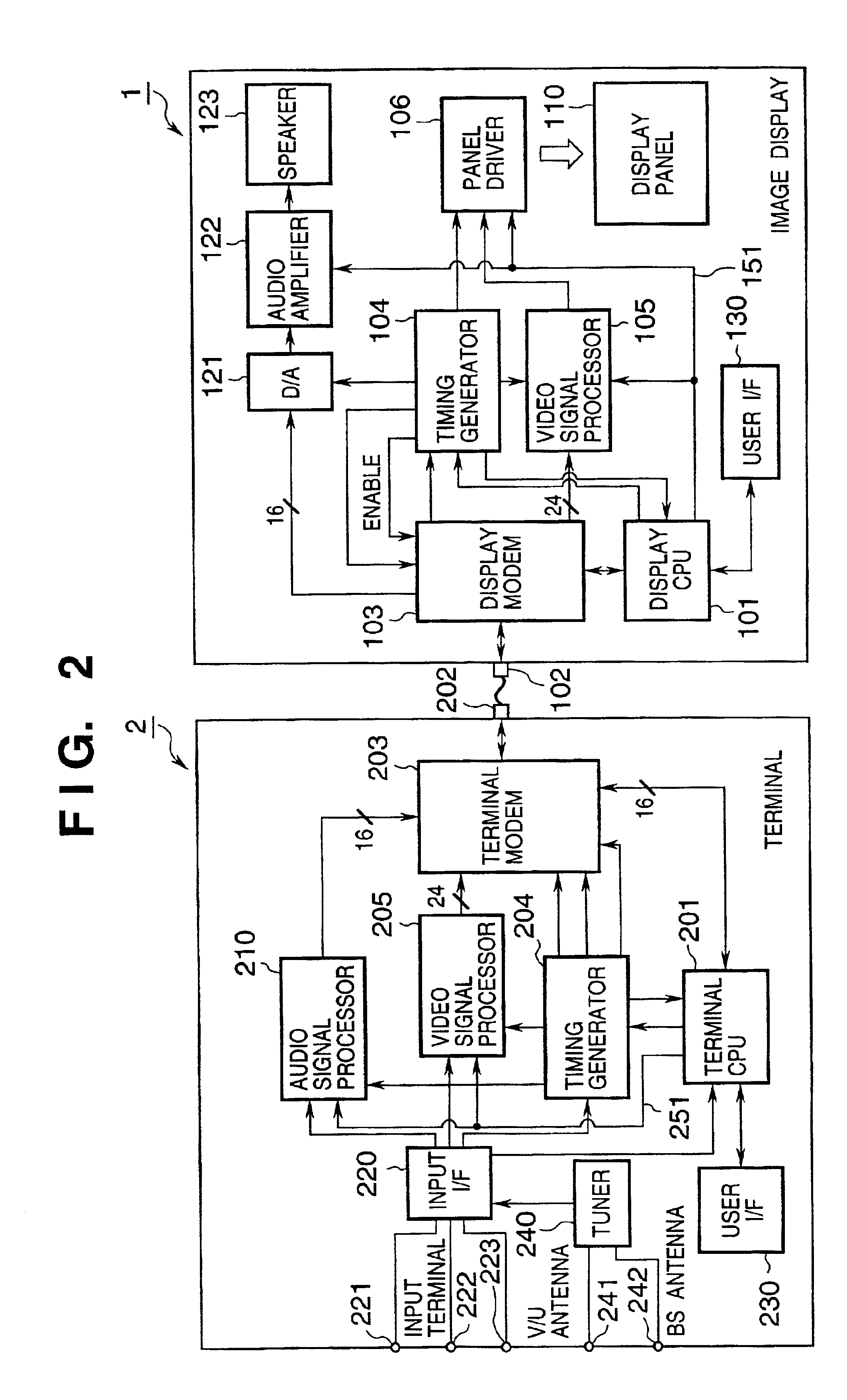
[0235]The second embodiment according to the present invention in which another optional device, e.g., a video printer is connected to one terminal or image display will be described with reference to FIGS. 26 to 28. In the second embodiment, the same reference numerals as in the first embodiment denote the same parts, and a detailed description thereof will be omitted. Also in the second embodiment, exchange of various data between the image display 1 and termin...

third embodiment

[0252]In the second embodiment, the dedicated modem and connection line are employed for the optional device 1100 in order to connect the optional device 1100. However, when the optional device is not one which need not emergently transmit / receive a large amount of information in real time, for example, when the optional device is a video printer, the dedicated modem and connection line need not be necessarily adapted for the optional device 1100.

[0253]Even when the optional device is connected to the image display, information for the optional device is controlled to be multiplexed and communicated using the idle time of information communication between the terminal and image display.

[0254]The third embodiment according to the present invention in which communication between the optional device and terminal is executed during the idle time of communication between the terminal and image display even when the optional device is connected to the image display will be described with ...


PUM


Abstract

This invention discloses an arrangement allowing connection of various kinds of image displays to one supply source in an image display control system having a supply source for transmitting a signal including at least a video signal, and an image display for receiving the signal and displaying a corresponding image. The supply source acquires characteristic data of the image display when it is powered on, determines a signal communication specification with the image display based on the acquired characteristic data, and communicates a signal including the video signal with the determined communication specification. The image display transmits characteristic data for specifying the characteristics of the image display to the supply source, and communicates the signal including the video signal in accordance with the determined communication specification. This invention also discloses an arrangement permitting changing the specifications and version of the control program of the image display.

Description

FIELD OF THE INVENTION[0001]The present invention relates to an image display control system having a supply source for transmitting a signal including at least a video signal, and an image display for receiving a signal from the supply source and displaying a corresponding image, and an image display system control method.BACKGROUND OF THE INVENTION[0002]FIG. 49 shows an arrangement used to display various images on a television receiver for receiving and displaying a conventional television program. As shown in FIG. 49, the television receiver is conventionally connected to a terrestrial television broadcasting (VHS / UHF) antenna line and satellite broadcasting (BS) antenna line as antenna lines. As cables extending from other display information supply sources, the television receiver is connected to signal cables such as a video signal line and acoustic signal line from a video cassette recorder, a video signal line and acoustic signal line from an LD / DVD playback apparatus, and ...

Claims


Application Information

Patent Timeline
Patent Type & Authority Patents(United States)
IPC IPC(8): H04N3/27H04N5/44H04N5/46
CPCH04N5/44H04N5/46H04N21/4122H04N21/42202H04N21/4318H04N21/43615H04N21/4363H04N21/4396H04N21/4398H04N21/4402H04N21/4621H04N21/4622H04N21/472H04N21/6581H04N21/8352
Inventor MORI, MAKIKOABE, NAOTOYAMAZAKI, TATSUROANDO, MUNEKI
Owner CANON KK
Why Eureka
Try Eureka