

Frictional surface apparatus for one handed dispensing of paper sheet segments
- Summary
- Abstract
- Description
- Claims
- Application Information
AI Technical Summary
Benefits of technology
Problems solved by technology
Method used
Image

Examples
Embodiment Construction
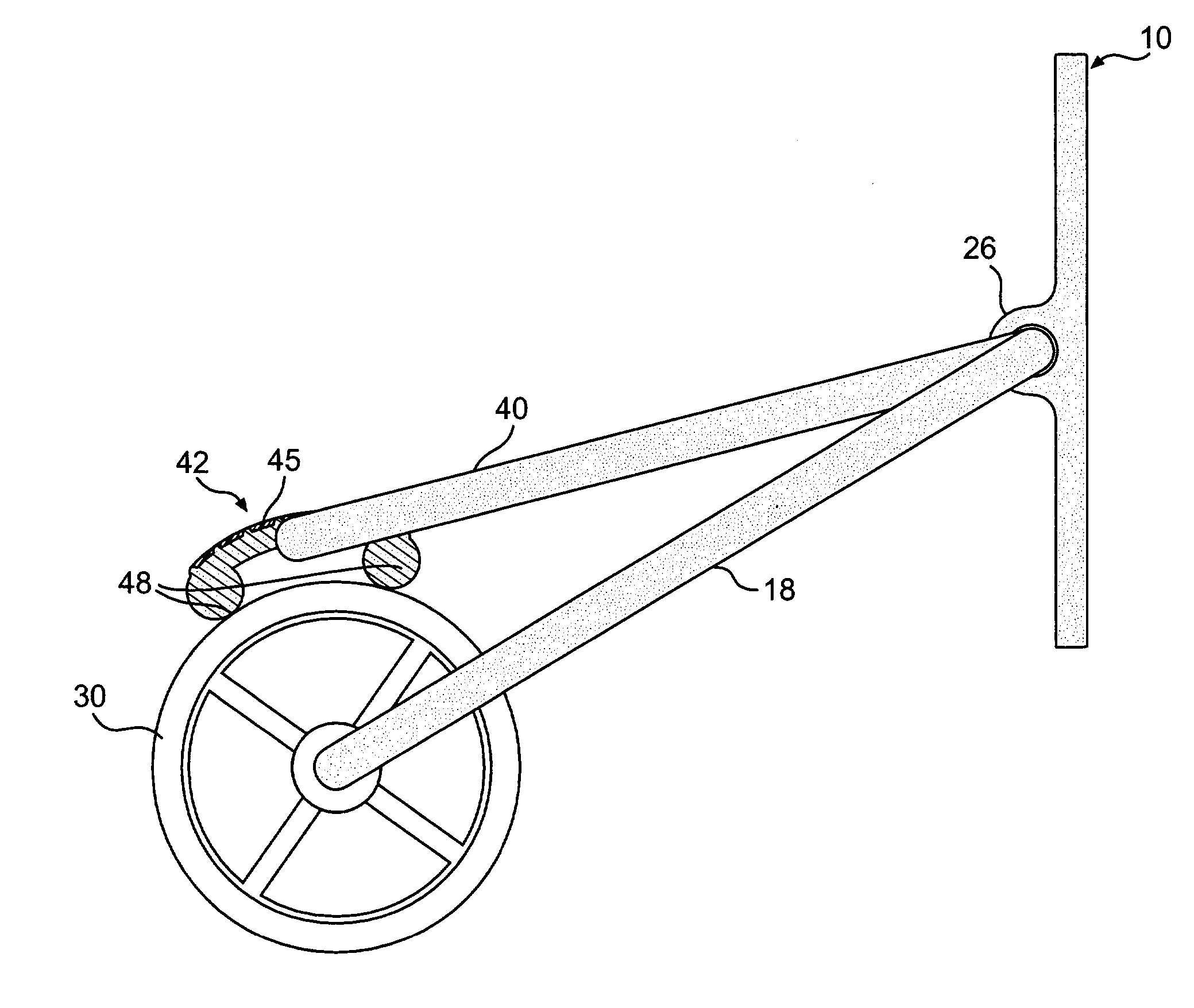
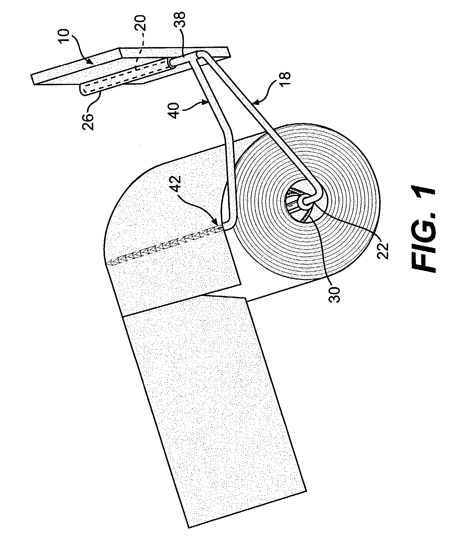
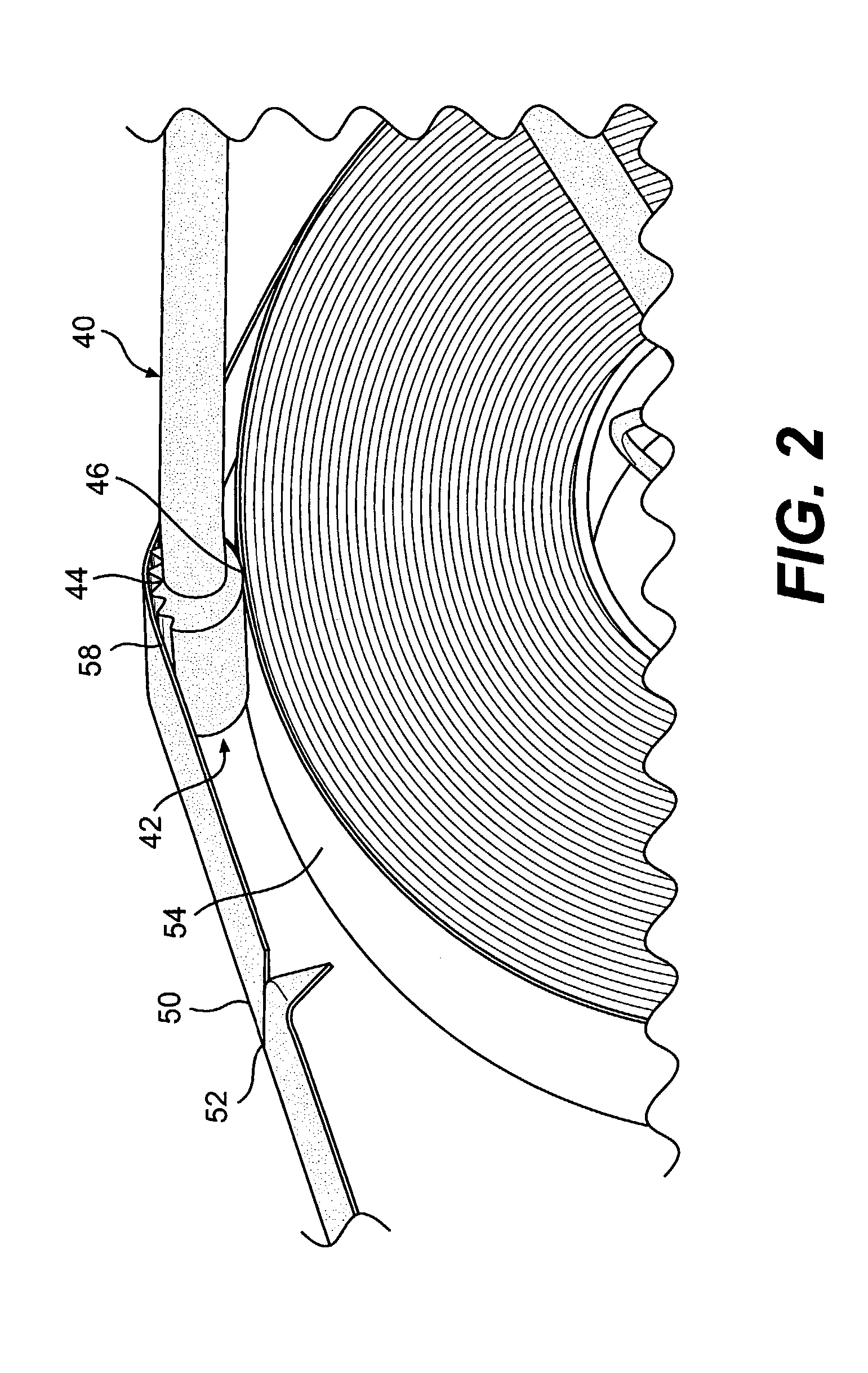
[0027]A preferred embodiment of the invention, which is intended to accomplish at least some of the foregoing objects, includes a single hand, paper sheet dispenser comprising a base, a core holder operable to rotatably hold a roll of segmented, paper sheet segments connected together end-to-end along perforated tear lines, and a single hand paper sheet dispensing bale. The single hand dispensing bale includes a high friction gripping member. The frictional gripping member of the dispensing bale is positioned between an external surface of a roll of paper sheets and an interior surface of an unreeled free end of the roll. Accordingly, the frictional gripping member allows a number of paper sheets to be dispensed while operably securing the roll in position by having a frictional outer surface segment and at least one arcuate inner surface segment, such that individual sheets of a segment paper sheet roll can be facilely dispensed with one hand.
DRAWINGS
[0028]Other objects and advanta...
PUM
| Property | Measurement | Unit |
|---|---|---|
| Friction | aaaaa | aaaaa |
Abstract
Description
Claims
Application Information