Image forming apparatus

a technology of image forming apparatus and forming tube, which is applied in the direction of electrographic process apparatus, instruments, optics, etc., can solve the problems of reducing productivity, affecting the quality of the patch image,

Active Publication Date: 2006-08-15
CANON KK
View PDF4 Cites 4 Cited by
  • Summary
  • Abstract
  • Description
  • Claims
  • Application Information

AI Technical Summary

Benefits of technology

[0017]It is an object of the present invention to provide an image forming apparatus in which the amount of toner supplied to a developing device can be made proper even if the amount of remaining toner in a toner container becomes small.
[0018]It is also an object of the present invention to provide an image forming apparatus in which the amount of toner supplied to a developing device can be made proper in accordance with the output of a density sensor.
[0019]It is also an object of the present invention to provide an image forming apparatus having a developing device for developing an electrostatic image formed on an image bearing member in accordance with an image signal with a developer including a toner and a carrier, a toner container containing the toner therein, a supplying member for supplying the toner from the toner container to the developing device, and controlling means for controlling an amount of toner supply to the developing device in accordance with the image signal, wherein when the amount of remaining toner in the toner container is small, the driving time of the supplying member conforming to the image signal is lengthened.

Problems solved by technology

Also, when the patch detecting method is adopted for the toner density control of a two-component developer, it is desirable to widen the interval at which the patch images are formed to the utmost, from the point that consumption of excess toner becomes necessary to form the patch images, and the point that the ordinary image forming operation must be discontinued during the formation of the patch images and this becomes a factor which reduces productivity.
On the other hand, when there is a difference between the toner consumption amount foreseen from the video count number and the actual toner consumption amount, there is the possibility that the toner density in the developer gradually deviates from a proper range.
This method, however, performs toner presence or absence detection and toner density control by a single sensor and therefore, simply by looking at the detection output of the patch image, it is difficult to judge whether the toner is truly absent or the density of the patch image has become low due to any other factor than the toner density.

Method used


Image

  • Image forming apparatus
  • Image forming apparatus
  • Image forming apparatus

Examples


first embodiment

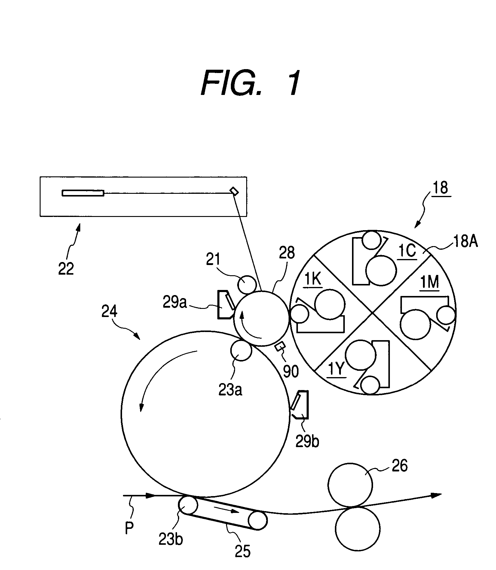
[0030]An embodiment of the image forming apparatus according to the present invention will first be described. The image forming apparatus of the present embodiment, as shown in FIG. 1, has a photosensitive drum 28 which is an electrophotographic photosensitive member as an image bearing member carried for rotation in the direction of arrow, and is provided with a primary charging device 21, developing means 18, an intermediate transfer member 24, a cleaner 29a and an exposing apparatus 22 around the photosensitive drum.

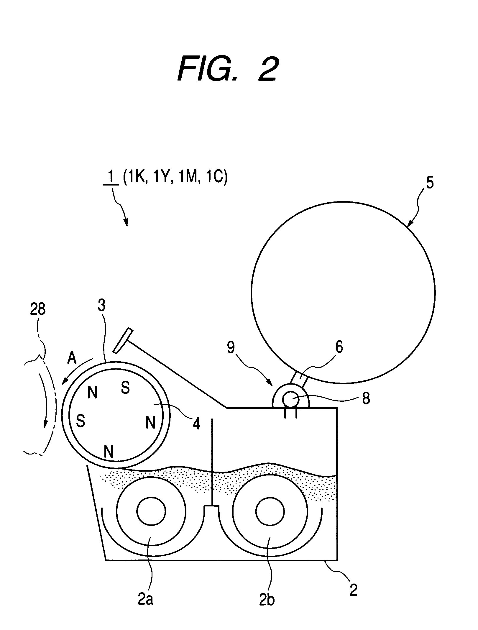
[0031]In the present embodiment, the developing means 18 disposed in opposed relationship with the photosensitive drum 28 is developing means of a rotary developing type, and is provided with a rotary member 18A rotatively driven by a motor (not shown). The rotary member 18A carries thereon four developing apparatuses 1 in the present embodiment, i.e., a developing apparatus 1K for black, a developing apparatus 1Y for yellow, a developing apparatus 1M for magenta, an...

second embodiment

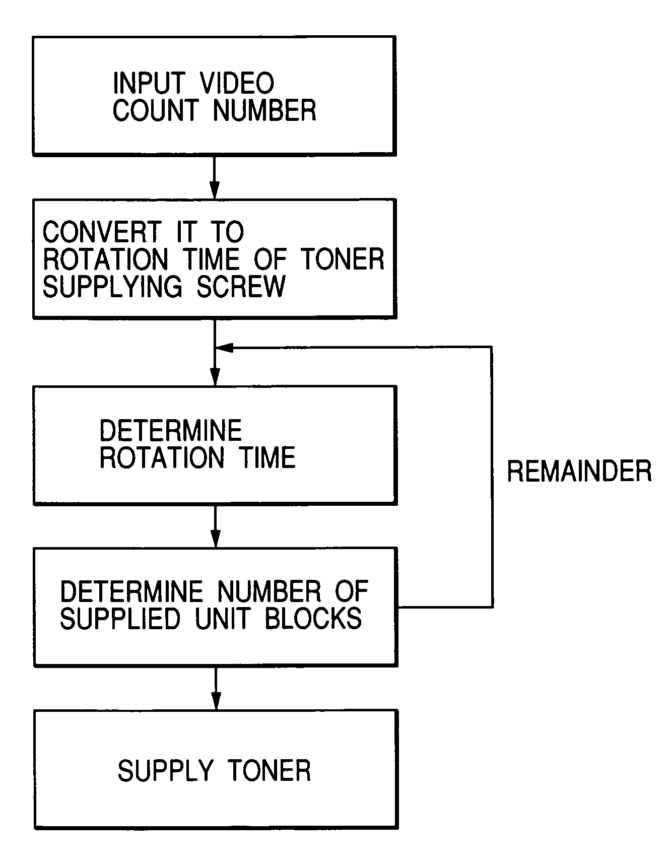
[0084]Again in this embodiment, in an image forming apparatus similar in construction to that described in the first embodiment, the toner supplying method is carried out with the number of supplied unit blocks added per sheet of image as described in the first embodiment, but the present embodiment is characterized in that in addition to it, if the density signal Vsig of the standard toner image detected in the patch detecting mode is below the density signal lower limit value Vlimit, when calculating the correction amount of the rotating time of the toner supplying screw 8 obtained from the difference between the initial reference signal Vref and the density signal Vsig, the correction percentage thereof is heightened.

[0085]That is, in the present embodiment, the density signal lower limit value is set to 4.5% in terms of toner density conversion, but when Vsig is greater than the lower limit value Vlimit, the above-mentioned correction percentage is set to 70%. The correction per...

third embodiment

[0091]The construction of the image forming apparatus and the method of adding the number of supplied unit blocks per sheet of image in this embodiment are similar to those in the first embodiment and the second embodiment, but the present embodiment is characterized in that in addition to them, when the density signal Vsig of the standard toner image detected in the patch detecting mode is equal to or less than the density signal lower limit value Vlimit, weighting is effected on the video count number of the density signal of an image information signal in first toner supply controlling means, and the driving time of the toner supplying portion is controlled on the basis of the weighted video count number.

[0092]In the present embodiment, as in the first embodiment and the second embodiment, the density signal lower limit value is set to 4.5% in terms of toner density conversion. When Vsig is greater this lower limit value, the rotating time of the toner supplying screw and the num...


PUM


Abstract

This invention realizes and provides an image forming apparatus in which the presence or absence of a toner remaining in a toner storing portion is judged by a patch detecting method, characterized in that the wrong detection of the judgment of the presence or absence of the toner can be prevented and the lowering of image density can be suppressed. In an image forming apparatus having a first toner supply controller for controlling the driving time of a toner supplying portion on the basis of the video count number of the density signal of an image information signal, and a second toner supply controller for correcting the driving time of the toner supplying portion determined by the first toner controller, and designed such that the presence or absence of the toner remaining in the toner storing portion is judged on the basis of the density signal of a standard toner image, when the density signal of the standard toner image is equal to or less than a predetermined value, the driving time of the toner supplying portion additionally corrected per image by the second toner supply controller is made longer than when the density signal of the standard toner image is greater than the predetermined value.

Description

BACKGROUND OF THE INVENTION[0001]1. Field of the Invention[0002]The invention relates to an image forming apparatus using an electrophotographic process, an electrostatic recording process or the like, and particularly to an image forming apparatus such as a copying machine, a printer or a facsimile apparatus, or a compound machine having a plurality of these functions.[0003]2. Related Background Art[0004]In conventional image forming apparatuses of an electrophotographic type, and above all, particularly a multi-color image forming apparatus for effecting color image forming, there has been widely utilized two-component development using a mixture of a nonmagnetic toner and a magnetic carrier as a developer.[0005]The two-component development, as compared with presently proposed other developing processes, has such merits as the stability of image and the durability of apparatus, while on the other hand, only the toner is consumed with image forming and therefore, in conformity the...

Claims


Application Information

Patent Timeline
Patent Type & Authority Patents(United States)
IPC IPC(8): G03G15/08G03G15/00G03G15/06G03G15/14G03G21/14
CPCG03G15/0822G03G2215/0609G03G2215/00037
Inventor SUZUKI, HIDEAKI
Owner CANON KK
Why Eureka
Try Eureka