Hybrid vehicles

a hybrid vehicle and hybrid technology, applied in the direction of combustion air/fuel air treatment, electric devices, braking components, etc., can solve the problems of increasing certain undesirable pollutants, ethanol has not become economically competitive with gasoline, and the effort to solve these problems is conflicting, etc., to achieve high efficiency, extend load-carrying capabilities, and broaden the utility range of vehicles

Inactive Publication Date: 2006-09-12
HIRSCH DAVID +1
View PDF440 Cites 193 Cited by
  • Summary
  • Abstract
  • Description
  • Claims
  • Application Information

AI Technical Summary

Benefits of technology

[0069]It is an object of the invention to provide an improved hybrid electric vehicle realizing substantially increased fuel economy and reduced pollutant emissions as compared to present day internal combustion and hybrid vehicles while suffering no significant penalty in performance, operating convenience, cost, complexity, or weight, which can be operated efficiently by an operator accustomed to conventional vehicles without special training, and which does not require modification of the existing infrastructure developed over the years to support conventional vehicles.

Problems solved by technology

To a degree, efforts to solve these problems conflict with one another.
However, higher combustion temperatures in gasoline-fueled engines lead to increase in certain undesirable pollutants, typically NOx.
However, to date ethanol has not become economically competitive with gasoline, and consumers have not accepted ethanol to any great degree.
Moreover, to make an alternate fuel such as ethanol available to the extent necessary to achieve appreciable improvements in nationwide air quality and fuel conservation would require immense costs for infrastructure improvements; not only the entire nation's motor fuel production and delivery system, but also the vehicle manufacture, distribution, and repair system, would have to be extensively revised or substantially duplicated.
To date, all such “straight electric” cars have had very limited range, typically no more than 150 miles, have insufficient power for acceleration and hill climbing except when the batteries are substantially fully charged, and require substantial time for battery recharging.
Thus, while there are many circumstances in which the limited range and extended recharging time of the batteries would not be an inconvenience, such cars are not suitable for all the travel requirements of most individuals.
Accordingly, an electric car would have to be an additional vehicle for most users, posing a substantial economic deterrent.
Moreover, it will be appreciated that in the United States most electricity is generated in coal-fired power plants, so that using electric vehicles merely moves the source of the pollution, but does not eliminate it.
Furthermore, comparing the respective net costs per mile of driving, electric vehicles are not competitive with ethanol-fueled vehicles, much less with conventional gasoline-fueled vehicles.
Accordingly, all vehicles driven directly by an internal combustion engine (other than certain single-speed vehicles using friction or centrifugal clutches, and not useful for normal driving) require a variable-ratio transmission between the engine and the wheels, so that the engine's torque can be matched to the road speeds and loads encountered.
It would not be practical to provide a diesel locomotive, for example, with a multiple speed transmission, or a clutch.
Moreover, such locomotives tend to be run at steady speeds for long periods of time.
However, such a direct drive vehicle would not achieve good fuel efficiency in typical automotive use, involving many short trips, frequent stops in traffic, extended low-speed operation and the like.
However, energy transfer between those components consumes at least approximately 25% of engine power.
Further, such components add substantially to the cost and weight of the vehicle; in particular, an electric motor capable of providing sufficient torque to meet all expected demand, e.g., to allow reasonable performance under acceleration, during hill-climbing and the like, is rather heavy and expensive.
Thus, series hybrid vehicles have not been immediately successful.
This arrangement is a source of additional complexity, cost and difficulty, as two separate modes of engine control are required.
Such a complex vehicle is unsuited for the automotive market.
Further, the gear train shown by Berman et al appears to be quite complex and difficult to manufacture economically.
Furthermore, the primary means of battery charging disclosed by Hunt involves a further undesirable complexity, namely a turbine driving the electric motor in generator configuration.
Hunt's internal combustion engine is also fitted with an alternator, for additional battery charging capability, adding yet further complexity.
More particularly, the latter Kawakatsu patent asserts that a single electric motor sized to provide sufficient torque to propel the vehicle would not be capable of providing sufficient regenerative braking force; see col.
More specifically, for reasons of safety and in accordance with industry practice, currents in excess of about 50 amperes cannot be carried by the conventional plug-in connectors preferred for reasons of convenience and economy, but must be carried by much heavier, more expensive and less convenient fixed connectors (as used on conventional starter and battery cable connections).
This arrangement would be complex and expensive to manufacture.
Kalberlah then compares various forms of parallel hybrids, with respect to his FIG. 4, and concludes that the most practical arrangement is one in which an internal combustion engine drives a first pair of wheels, and an electric motor the second; more particularly, Kalberlah indicates that mechanical combination of the torque from an internal combustion engine and an electric motor is impractical.
The Urban et al design appears to suffer from a number of significant defects.
Such components are clearly complex and expensive; further, torque converters are notoriously inefficient.
Moreover, using the internal combustion engine as the sole source of power for low-speed running would require it to be run at low speeds, e.g., at traffic lights, which is very inefficient and highly polluting.
(Various additional references suggest that excess torque can be used to charge batteries; if this were incorporated in the Urban system, the engine might be run at a reasonably efficient output level while the vehicle was stationary, but this would lead to high levels of noise and vibration.
On the other hand, Urban does suggest that the vehicle can be operated as a “straight electric” under low-speed conditions, but this requires the operator to provide an explicit control input; this complexity is unacceptable in a vehicle intended to be sold in quantity, as would be required in order to reach Urban's stated goals of reduction of atmospheric pollution and reduced energy consumption.
It will be appreciated by those of skill in the art that there are significant limitations inherent in the use of planetary gearsets as a means for connecting different sources, e.g., an internal combustion engine and an electric motor, to the drive wheels of a vehicle, namely, that unless the planetary gearset is effectively locked (anathematic to its use as a continuously-variable transmission, e.g., in the Toyota vehicle) it is capable of additive combination of shaft speeds, but not of output torque.
If the vehicle's operational mode is selected based solely on speed, as taught by Koide and Schmidt-Brücken, it will be incapable of responding to the operator's commands, and will ultimately be unsatisfactory.
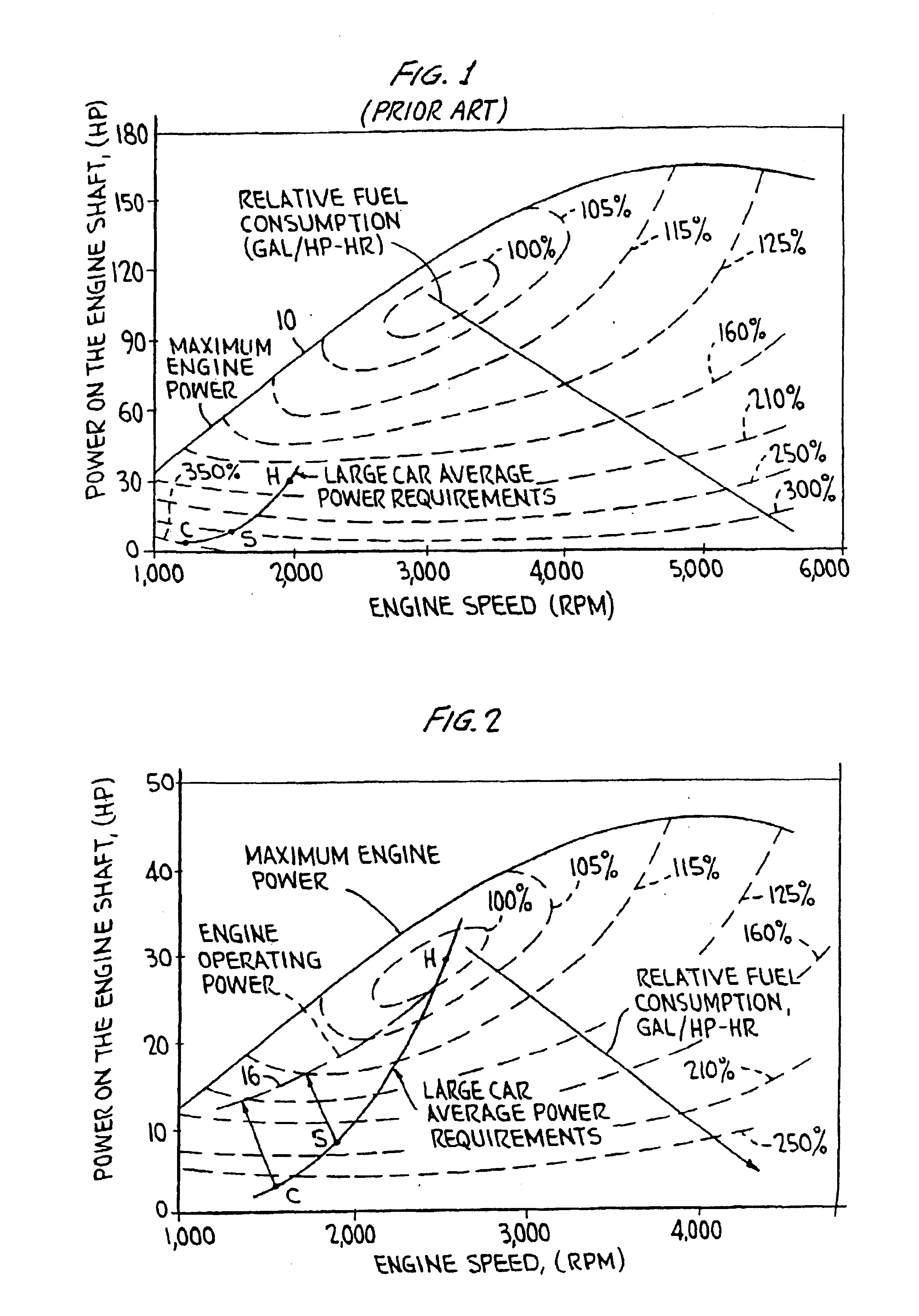
Therefore the engine is never operated at less than 30% of MTO, and is thus never operated inefficiently.
Moreover, despite making reference to a “vehicle driving torque demand Mv*”, which might be misunderstood to be equivalent to applicant's road load, Egami in fact does not determine the road load.

Method used


Image

  • Hybrid vehicles
  • Hybrid vehicles
  • Hybrid vehicles

Examples


Embodiment Construction

[0126]Referring specifically to FIG. 1, which is reproduced here from the '970 patent for convenience, curve 10 represents the output power versus engine speed (RPM) of a typical spark ignition gasoline-fueled internal combustion engine as used with an automatic transmission in a typical sedan of 3,300 pounds. As can be seen, the maximum engine power available is about 165 horsepower at about 5,000 RPM. Also shown in FIG. 1 by the curve labeled “Large Car Average Power Requirements” are the average power requirements of such a vehicle. Points C, S, and H on this curve show average fuel consumption in city, suburban, and highway driving, respectively; in particular, point C shows that the average power required in typical city driving is less than 5 hp. Point S shows that the average power consumed in suburban driving is 10 hp, and point H shows that the power needed for steady-speed highway driving is only about 30 hp. Thus, the vehicle is vastly overpowered at all times except duri...


PUM


Abstract

A hybrid vehicle comprises an internal combustion engine, a traction motor, a starter motor, and a battery bank, all controlled by a microprocessor in accordance with the vehicle's instantaneous torque demands so that the engine is run only under conditions of high efficiency, typically only when the load is at least equal to 30% of the engine's maximum torque output. In some embodiments, a turbocharger may be provided, activated only when the load exceeds the engine's maximum torque output for an extended period; a two-speed transmission may further be provided, to further broaden the vehicle's load range. A hybrid brake system provides regenerative braking, with mechanical braking available in the event the battery bank is fully charged, in emergencies, or at rest; a control mechanism is provided to control the brake system to provide linear brake feel under varying circumstances.

Description

CROSS-REFERENCE TO RELATED APPLICATIONS[0001]This application is a divsional of Application Ser. No. 09 / 822,866, filed Apr. 2, 2001, now U.S. Pat. No. 6,554,088 which is a continuation-in-part of Ser. No. 09 / 264,817, filed Mar. 9, 1999, now U.S. Pat. No. 6,209,672, issued Apr. 3, 2001, which in turn claims priority from provisional application Ser. No. 60 / 100,095, filed Sep. 14, 1998, and is also a continuation-in-part of Ser. No. 09 / 392,743, filed Sep. 9, 1999 now U.S. Pat. No. 6,338,391, which in turn claims priority from provisional application Ser. No. 60 / 122,296, filed Mar. 1, 1999.FIELD OF THE INVENTION[0002]This application relates to improvements in hybrid vehicles, that is, vehicles in which both an internal combustion engine and one or more electric motors are provided to supply torque to the driving wheels of the vehicle. More particularly, this invention relates to a hybrid electric vehicle that is fully competitive with presently conventional vehicles as regards perform...

Claims


Application Information

Patent Timeline
Patent Type & Authority Patents(United States)
IPC IPC(8): B60K6/02B60H1/32B60K1/02B60K6/442B60K6/48B60L15/20B60L50/15B60L50/16B60W10/06B60W10/08B60W10/18B60W10/26F01N3/20F02B37/00F02B37/16F02B37/18F02D41/00F02M35/10
CPCB60H1/004B60H1/3222B60K6/442B60K6/48B60L11/123B60L11/14B60L11/1861B60L15/2045B60W10/06B60W10/08B60W10/18B60W10/26B60W20/00F01N3/2013F02B37/00F02B37/16F02B37/18F02D41/0007F02M35/10163B60K6/46B60L11/1811B60L11/1851B60K6/485B60K6/547B60K6/365B60W20/30B60W20/108B60K1/02B60L2210/20B60L2220/12B60L2220/14B60L2220/16B60L2240/34B60L2240/36B60L2240/423B60L2240/443B60L2240/445B60L2260/28B60L2270/145B60W2510/0633B60W2510/0657B60W2510/244B60W2530/16F02D2250/18F02M35/10157F02N11/0818F02N2200/061Y02T10/6217Y02T10/6221Y02T10/6234Y02T10/6286Y02T10/7005Y02T10/7044Y02T10/705Y02T10/7077Y02T10/725Y02T10/7283Y02T10/144Y02T10/26Y10S903/93Y10S903/946Y10S903/947Y10S903/904Y02T10/642B60Y2400/435Y10S903/903B60L2200/26Y10T477/23Y10T477/24B60W20/15B60L50/61B60L50/16B60L53/00B60L53/20B60L58/10B60L58/12Y10S903/907Y02A50/20Y02T10/12Y02T10/62Y02T10/64Y02T10/70Y02T10/72Y02T10/7072Y02T90/14Y02E60/10B60K2006/268B60W20/10B60L7/18B60T2270/604B60L7/26B60T13/586H01M10/4207H01M2220/20B60K6/22B60W30/18127B60W2540/12B60W2710/08B60W2710/18B60W2710/244B60Y2200/91B60Y2200/92B60Y2300/18125B60Y2300/91B60Y2400/81B60W20/14B60T7/06B60T8/17B60T8/172B60T11/18B60T2270/60B60Y2400/112
Inventor SEVERINSKY, ALEX J.LOUCKES, THEODORE
Owner HIRSCH DAVID
Why Eureka
Try Eureka