Coordinate inputting/detecting apparatus and method designed to avoid a trailing phenomenon

a technology of inputting/detecting apparatus and detection device, which is applied in the direction of mechanical pattern conversion, visual presentation, instruments, etc., can solve the problems of increasing the manufacturing cost of the apparatus, increasing the difficulty of operation, and breaking the line, so as to reduce the trailing phenomenon

Inactive Publication Date: 2006-09-26
RICOH KK
View PDF20 Cites 50 Cited by
  • Summary
  • Abstract
  • Description
  • Claims
  • Application Information

AI Technical Summary

Benefits of technology

[0017]Preferred embodiments of the present invention provide a novel coordinate inputting/detecting apparatus and method that precisely recognize a designatin...

Problems solved by technology

However, in such a coordinate inputting/detecting apparatus that detects a coordinate position using an electrostatic force or an electromagnetic induction, an electrical switching function must be provided at a coordinate inputting surface of the coordinate inputting/detecting apparatus, thus increasing the manufacturing cost of the apparatus.
Further, the pen must be connected to a main body of the apparatus, for example by a cable, which makes the operation relatively difficult.
When a pen made of soft elastic material is used for the designating device, in writing a straight line with the pen on a panel, for example, although the attenuation of a surface elastic wave is reliably obtained when the pen is pressed against the panel, a sufficient contact of the pen with the panel is not obtained when the pen is moved, and thereby the line is broken.
On the other hand, if the pen is pressed unnecessarily strongly while moving the pen for obtaining the sufficient contact with the panel, as the pen is moved, the panel receives a stress from the pen because of the elasticity of the pen.
This causes a distortion i...

Method used


Image

  • Coordinate inputting/detecting apparatus and method designed to avoid a trailing phenomenon
  • Coordinate inputting/detecting apparatus and method designed to avoid a trailing phenomenon
  • Coordinate inputting/detecting apparatus and method designed to avoid a trailing phenomenon

Examples


Embodiment Construction

[0045]Referring now to the drawings, wherein like reference numerals designate identical or corresponding parts throughout the several views, preferred embodiments of the present invention are described.

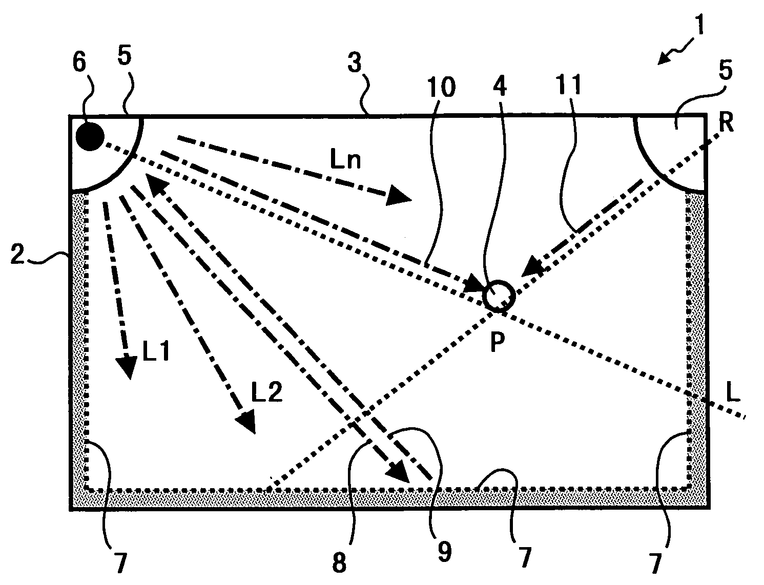
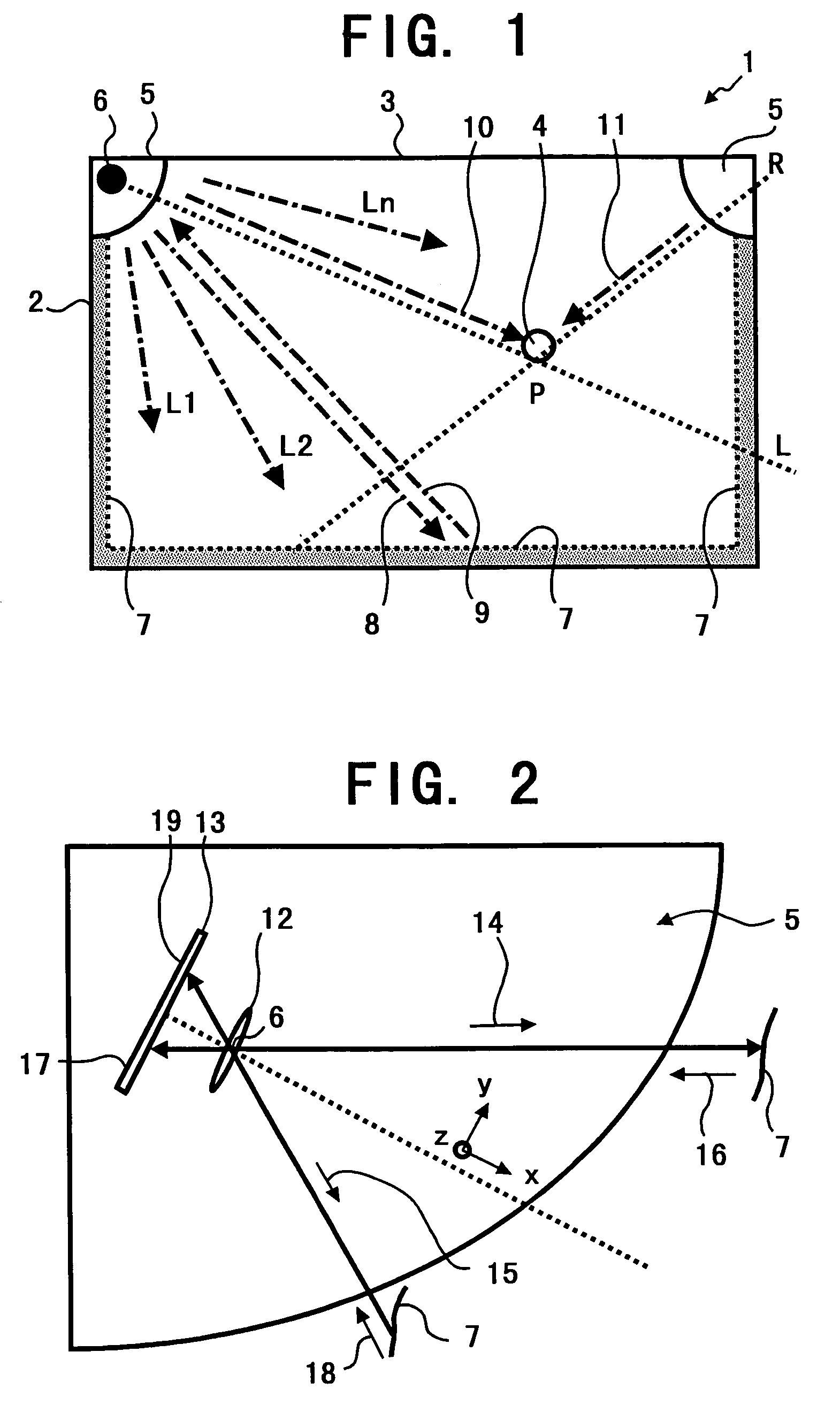
[0046]First, an exemplary construction of a coordinate inputting / detecting apparatus to which the present invention is applied is described referring to FIGS. 1–6. FIG. 1 is a front view illustrating a construction of a coordinate inputting / detecting apparatus 1 employing a so-called returning light interrupting method. A coordinate inputting / detecting area 3, which is an internal space of a coordinate inputting / detecting member 2 formed in a square shaped frame, is two-dimensionally shaped and is flat or substantially flat. The coordinate inputting / detecting area 3 may be formed, for example, by a display surface of a display apparatus that electronically displays information, e.g. a plasma display, or by a white board for writing information thereupon with a writing pen such as a m...


PUM


Abstract

A coordinate inputting/detecting apparatus in which a designating device for designating a position in a flat or substantially flat two-dimensional coordinate inputting/detecting area of the coordinate inputting/detecting apparatus is judged as located in a predetermined range of the coordinate inputting/detecting area when an optical detection signal of an optical unit, that optically detects the designating device inserted into the predetermined range of the coordinate inputting/detecting area, exceeds a first predetermined threshold value. Whether or not the designating device has been inserted into the predetermined range of the coordinate inputting/detecting area is judged and coordinates of the position in the coordinate inputting/detecting area, designated by the designating device inserted in the predetermined range of the coordinate inputting/detecting area, are recognized in accordance with the optical detection signal of the optical unit. A second threshold value is used in recognizing the coordinates of the position in the coordinate inputting/detecting area, designated by the designating device inserted in the predetermined range of the coordinate inputting/detecting area. The second threshold value is set to be higher than the first threshold value used in judging if the designating device has been inserted into the predetermined range of the coordinate inputting/detecting area.

Description

BACKGROUND OF THE INVENTION[0001]1. Field of the Invention[0002]The present invention relates to a coordinate inputting / detecting apparatus, and more particularly relates to an optical touch panel type coordinate inputting / detecting apparatus, that is integrated and used with an electronic white board or a large display apparatus, or used in conjunction with a personal computer, and that optically detects a coordinate position designated by a designating member, such as a pen, or a finger, for inputting or selecting information represented by the coordinate position designated by the designating member.[0003]2. Discussion of the Background[0004]A coordinate inputting / detecting apparatus is known in which, when a coordinate inputting surface of the coordinate inputting / detecting apparatus is pressed by a pen or when the pen approaches the coordinate inputting surface, an electrical change is caused by an electrostatic charge or an electromagnetic induction, and thereby the coordinate...

Claims


Application Information

Patent Timeline
IPC IPC(8): G09G5/00G06F3/042G06F3/041G06F3/0488
CPCG06F3/0421G06F3/0423Y10S345/902Y10S345/901
Inventor TAKEKAWA, KENICHISAKA, YASUHIKO
Owner RICOH KK
Why Eureka
Try Eureka