Method and apparatus for measuring distances using light

a technology of distance measurement and light, applied in distance measurement, height/levelling measurement, instruments, etc., can solve the problems of high noise into the overall system, too complex optics of lasers and optics in such approaches, and too expensive for budget limited or highly miniaturized applications, etc., to achieve the effect of convenient us

Inactive Publication Date: 2006-10-17
VORTANT TECH
View PDF18 Cites 47 Cited by
  • Summary
  • Abstract
  • Description
  • Claims
  • Application Information

AI Technical Summary

Benefits of technology

[0011](e) to provide a system to obtain images of distance data.
[0012]The present invention is a system for measuring the distance to an object, using light. The light intensity over multiple paths is measured and the relative light intensity from the paths is used to calculate the distance to the object. In some embodiments of the present invention, the light travels over paths of differing length between the light source(s), the object reflecting the light, and the light detector(s) and the light intensity measured by the light detector(s) generates electrical signals that are used to calculate the distance from the device to the object. In other embodiments of the present invention, the light travels over paths between the light source(s), the object reflecting the light, and the light detector(s) and the light intensity measured by the light detector(s) generates electrical signals that are used in connection with the offset angle effect to calculate the distance from the device to the object.
[0013]In one embodiment of the present invention, two or more light sources and one light detector are used. Light is sequentially transmitted from each source, and received at the light detector. In another embodiment of the present invention, one light source and two or more light detectors are used. Light is simultaneously received at both light detectors.
[0014]In another embodiment of the present invention, light is sequentially transmitted from two or more light sources, and an imaging device, such as a digital camera, is used to provide an array of distances containing distance information in each pixel.
[0015]While the distance measuring systems of the present invention may be used to measure various distances from distances less than 10 centimeters in length to distances up to or greater than 5 meters in length, the distance measuring system of the present invention provides an inexpensive, noncomplex, easy to use, distance measuring system that is particularly well suited for measuring and / or monitoring distances to an object wherein the distance from the distance measuring system to the object ranges from about 10 centimeters to about 5 meters. Over this preferred measurement range, the distance measuring system of the present invention has an accuracy of about ±10%.

Problems solved by technology

However, the lasers and optics in such approaches are too complex and expensive for budget limited or highly miniaturized applications.
Although such approaches use lower-cost LEDs and photosensitive diodes, relatively short, properly shaped pulses are required.
These factors introduce higher levels of noise into the overall system, thus relatively complex electronics circuitry or specialized, high power pulse generation at the LED is needed.
The basic approach is subject to problems with range and reliability, and various improvements have been described in the following patents.
However, these approaches still require the use of lenses in order to obtain images of light spots or patterns.
The need for lenses increases the bulk as well as the cost of a distance measuring system.

Method used


Image

  • Method and apparatus for measuring distances using light
  • Method and apparatus for measuring distances using light
  • Method and apparatus for measuring distances using light

Examples


embodiment 201

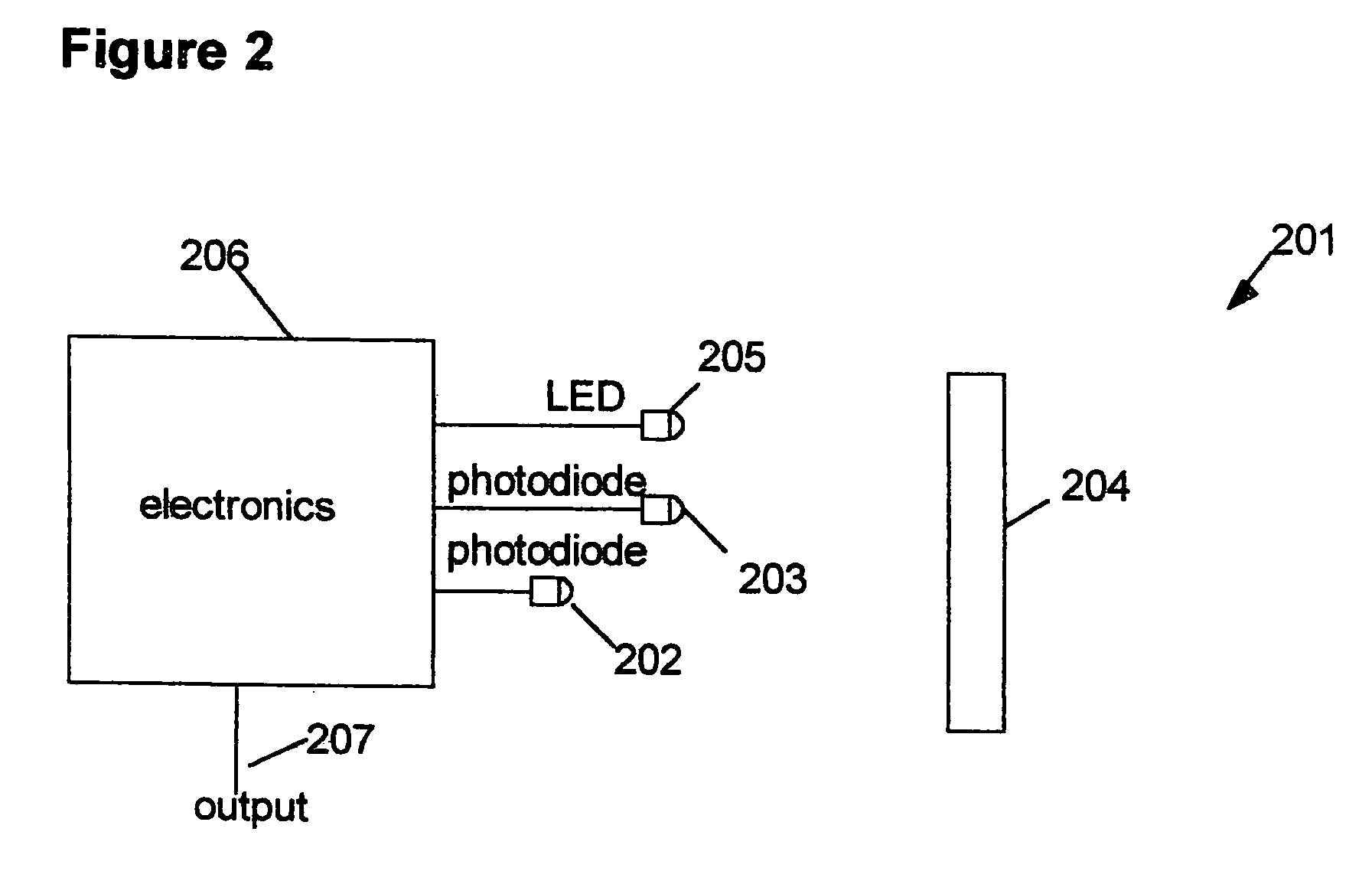
[0032]FIG. 2 shows a diagram of an alternate embodiment 201 of the distance measuring system of the present invention. In this embodiment, a single light source 205 is used to illuminate an object 204. Two light detectors 202 and 203, preferably photodiodes, are located at different direct (straight line) distances from the object 204. Preferably, the light detectors 202 and 203 and the light source 205 are located adjacent each other and contained in a single unit. Typically, the near light detector 203 is from 2 to 10 centimeters closer to the object 204 than the far light detector 202. Preferably, the light detectors 202 and 203 are located and oriented relative to each other and the light source 205 so that the light beam emitted by the light source 205 and the resulting reflected light beams from the object 204 detected by the light detectors 202 and 203 are substantially collinear over a distance measuring range selected for the system. The emitted light beams and the reflecte...

embodiment 101

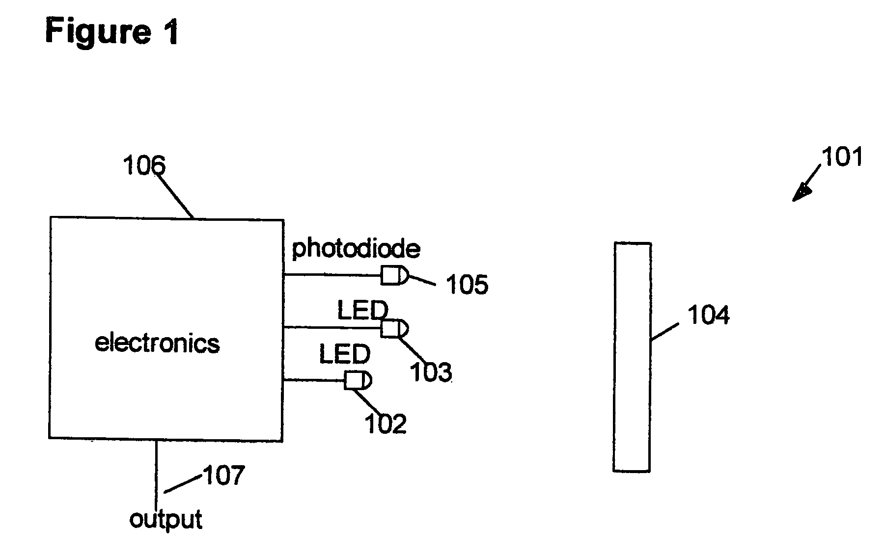
[0040]In all embodiments of the present invention described above, a set of two or more light intensity measurements are obtained for each distance measurement desired. The algorithm to calculate distances from the light intensities is described here in connection with embodiment 101, but applies equally to embodiments 201 and 301.

[0041]The algorithm is based on a mathematical illumination model. In the preferred embodiment of the invention, the algorithm is based on a diffuse reflection illumination model (see Foley & van Dam, “Fundamentals of Interactive Computer Graphics”, Addison-Wesley Publishing Company, Inc., ©) 1982, pp. 575–580). Preferably, if it is assumed that the direct (straight line) spacing between light sources 102 and 103 is given by D, the unknown distance from the light source 103 to object 104 is L, and the surface angle of object 104 with respect to the direction of light source 103 is Q, the light intensity detected by light detector 105 from light source 103,...


PUM


Abstract

A method and device for measuring a distance to an object with light determines the distance by measuring the relative intensity of light reflected from the object and traveling over two or more paths of differing optical length or reflected from the object and traveling over two or more paths through the use of the offset angle effect. Light is emitted by one or more light sources; reflected from a surface of the object; and the reflected light is detected by one or more light detectors. The light detector(s) generate signals based on the intensity of reflected light detected and the signals are utilized to calculate the distance from the device to the object.

Description

CROSS-REFERENCE TO RELATED APPLICATIONS[0001]This patent application is a continuation-in-part of copending U.S. patent application Ser. No. 10 / 641,850 filed Aug. 15, 2003, which prior application claimed the priority and benefit of U.S. Provisional Application No. 60 / 405,079, filed Aug. 20, 2002. This patent application also claims the priority and benefit of copending U.S. Provisional Application No. 60 / 625,035, filed Nov. 3, 2004, which is incorporated herein in its entirety by reference.GOVERNMENT LICENSE RIGHTS[0002]This invention was made with United States government support under one or more SBIR grants from the National Institutes of Health. The United States government has certain rights in this invention.BACKGROUND OF THE INVENTION[0003]The present invention relates to a method and device for measuring a distance from the device to an object using light, and, more specifically, to a method and device for measuring a distance from the device to an object wherein light is e...

Claims


Application Information

Patent Timeline
Patent Type & Authority Patents(United States)
IPC IPC(8): G01C3/08G01C3/00
CPCG01C3/08G01S17/08G01S7/4814
Inventor SCHAEFER, PHILIP R.
Owner VORTANT TECH
Why Eureka
Try Eureka