Box for storing fishing flies

a box and flies technology, applied in the field of boxes for storing flies, can solve the problems of not being able to be removed from the box, not being as waterproof as may be desired, and adding significant costs to the manufacturing and assembly of the box, etc., and achieves the effect of being easy to see and inexpensive to manufactur

Inactive Publication Date: 2007-01-30
SCI ANGLERS
View PDF24 Cites 18 Cited by
  • Summary
  • Abstract
  • Description
  • Claims
  • Application Information

AI Technical Summary

Benefits of technology

[0005]The present invention provides a box for storing flies used for fishing including (when closed) a cover assembly around a fly storage assembly. The fly storage assembly is removable from the cover assembly so that different fly storage assemblies can be positioned within the cover assembly, the cover assembly is transparent so that the type and quantity of flies on the fly storage assembly can be easily seen without opening the box, the cover assembly can be closed with one hand, the box when closed is waterproof, and the box is inexpensive to manufacture compared to the boxes for storing flies described above.
[0007]The layers of flexible sealing material on the major surfaces of the support plate in sealing engagement with the edge portions of the cover portions when the cover portions are in the closed position can be parts of a collar of the sealing material extending around the edge portion of the support plate, with the collar of the sealing material including lips of the sealing material adapted to extend around and engage the outer surfaces of the side wall parts of the cover portions when the cover portions are in their closed position. The lips have cam surfaces adjacent the cover portions when the cover portions are in their closed position that help to position the lips around and in engagement with the outer surfaces of the side wall parts and help to position the edge portions of the cover portions for proper engagement with the layers of flexible sealing material as the cover portions move from their open to their closed positions. With this structure the sealing engagement between the edge portions of the cover portions and the collar of the sealing material can be essentially water tight. Also, the central wall parts of the cover portions can be resiliently flexible, and with the cover portions in the closed position pressure can be applied to flex the central wall parts toward each other to expel air from within the box between the edge portions of the cover portions and the collar of the sealing material, thereby forming a partial vacuum in the box when the pressure is released. That vacuum will cause external air pressure to press the edge portions of the cover portions more firmly against the sealing material and increase the resistance to water entering the closed box.
[0011]The central fly retaining assembly can be distinctively colored (e.g., its support plate being green, blue, or yellow, and the material on its surfaces adapted to be releasably engaged by flies being grey, black or white). A person can then, for example, use fly retaining assemblies of one color on which to store a certain type of fly, and use fly retaining assemblies of another color to store a different type of fly, and so forth. The distinctive color of the central fly retaining assembly can be easily seen through the transparent cover portions so that a person can easily identify the fly box in which it is contained. Also, a person can have more fly retaining assemblies than cover assemblies, the excess fly retaining assemblies can be stored in a compact storage container, and the fly retaining assembly to which are attached flies the person wishes to use on a particular occasion can be inserted in the cover assembly and carried to the location (e.g., the stream) at which they are to be used.

Problems solved by technology

This box is made water proof by means including an O ring around an edge of the bottom portion engaged by the cover portion, and a secure latch assembly that extends the majority of the distance along one side of both portions, both of which add significant costs to manufacturing and assembling the box.
The cover portions on this box are at least semi-transparent so that the quantity and type of flies in the box can be somewhat seen without opening the box, and the box can be closed with one hand; however, the fly retaining assembly can not be removed from the box, and the box may not be as waterproof as may be desired.

Method used


Image

  • Box for storing fishing flies
  • Box for storing fishing flies
  • Box for storing fishing flies

Examples


Embodiment Construction

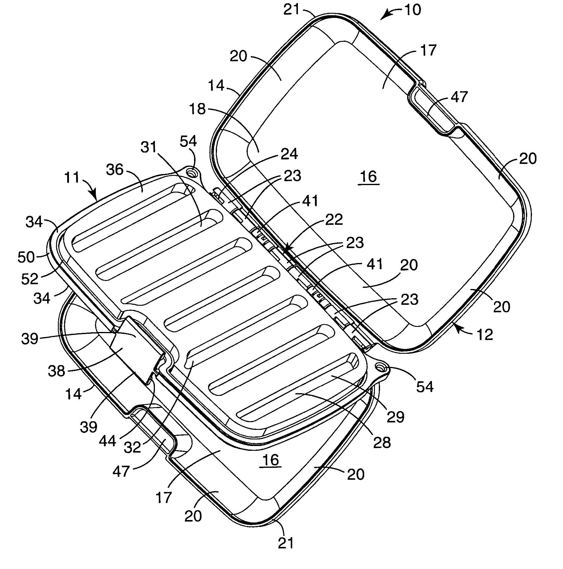
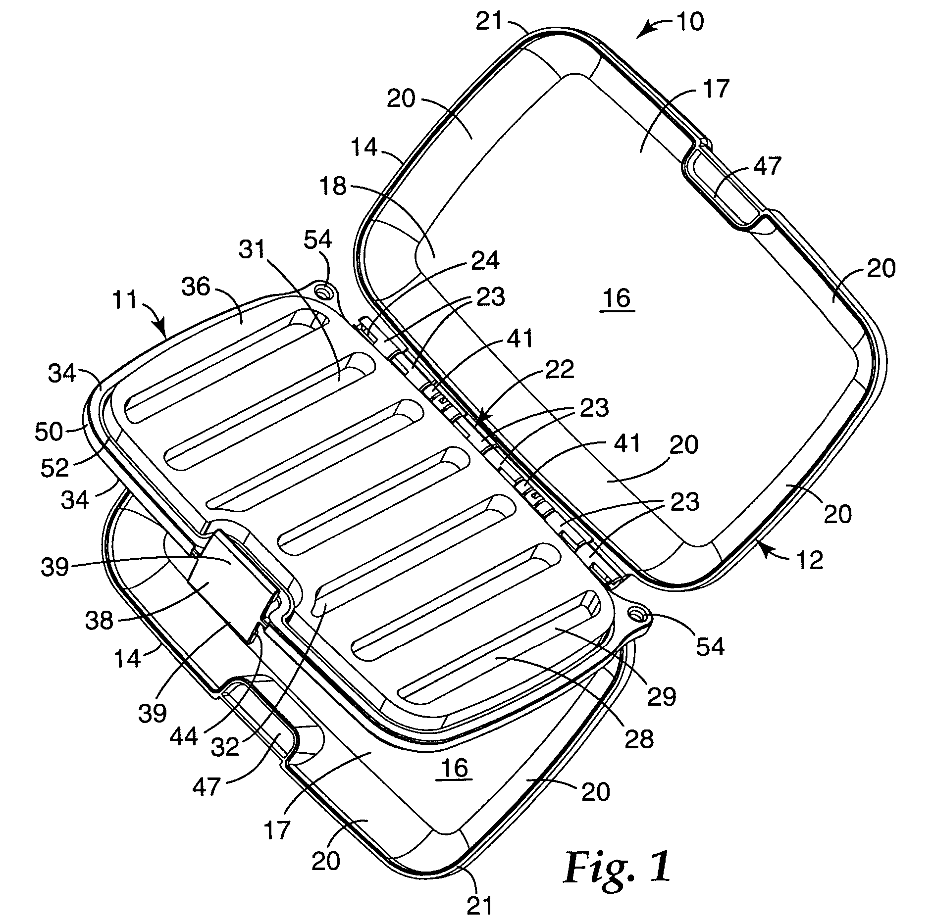
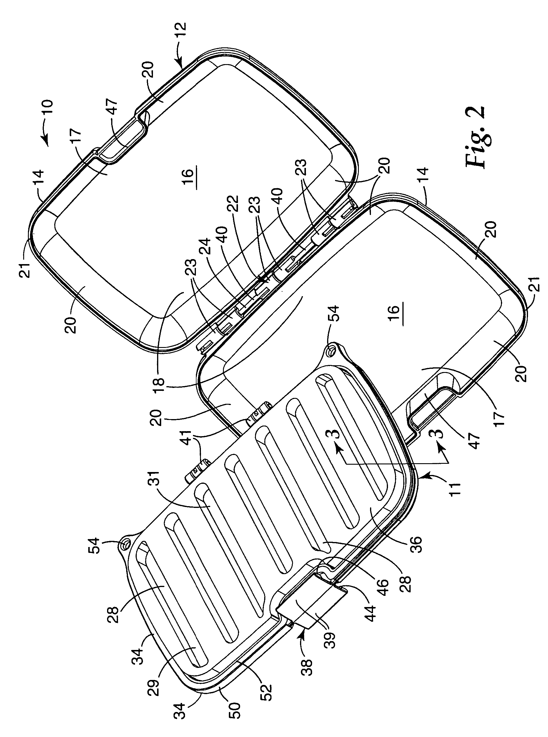
[0020]Referring now to the drawing there is illustrated a box according to the present invention that can be used for storing flies of the type used for fishing, which box is generally designated by the reference numeral 10. The box 10 includes a fly retaining assembly 11 that, as seen in FIGS. 1, 4, and 6, can be attached to and enclosed by a cover assembly 12, and, as seen in FIG. 2, can be removed and separated from the cover assembly 12.

[0021]The cover assembly 12 comprises two dish-like cover portions 14, each of which cover portions 14 is molded of a transparent polymeric material (e.g., 0.09 inch or 0.23 cm thick acrylonitrile-butadiene-styrene or ABS such as Toyolac 920 clear commercially available from Toray Resin Company, Charlotte, N.C.) and includes a central wall part 16 having a generally rectangular periphery with first and second opposite sides 17 and 18, and side wall parts 20 around the periphery of the central wall part 16 projecting generally in the same directio...


PUM


Abstract

A box for storing flies used for fishing including a cover assembly having two dish-like cover portions, each of which cover portions includes a central wall part, and side wall parts around the periphery of the central wall part projecting generally in the same direction away from the central wall part and having a continuous distal edge portion; and a hinge having hinge portions attached to the side wall parts adjacent second sides of the central wall parts. The hinge affords pivotal movement of the cover portions between a closed position with the distal edge portions of the cover portions opposed to, closely spaced from, and generally aligned with each other, and an open position with the distal edge portions spaced away from and out of alignment with each other. A fly retaining assembly included in the box comprises a stiff resiliently flexible support plate having opposite major surfaces that extends between the distal edge portions of the cover portions when the cover portions are in the closed position, and has material adapted to be releasably engaged by flies on each of its major surfaces. Releasably engageable means can be provided between the support plate and the hinge for affording pivotal movement of the fly retaining assembly relative to the hinge independent of the cover portions when the cover portions are in their open position. A layer of flexible sealing material can be provided by over molding on each of the major surfaces of the support plate that is in sealing engagement with the edge portion of the adjacent cover portion when the cover portions are in their closed position, and material adapted to be releasably engaged by flies is provided on each major surface of the support plate, in a position that will be surrounded by the side wall parts of the adjacent cover portion when the cover portions are in their closed position. A latch member is provided along a second side of the periphery of the support plate opposite its first side. That latch member has opposite portions each adapted for releasable engagement with a different one of the cover portions to releasably retain the cover portions in their closed position.

Description

FIELD OF THE INVENTION [0001]The present invention relates to boxes for storing flies used for fishing, which boxes are generally of the type including at least two portions, a hinge between the portions affording relative pivotal movement of the portions between open and closed positions, the portions defining at least one enclosed cavity between the portions when in the closed position, the box including material adapted to be releasably engaged by flies within the cavity and a latch mechanism for releasably retaining the housing portions in their closed position.BACKGROUND OF THE INVENTION [0002]Many boxes are known for storing flies used for fishing, which boxes are generally of the type including at least two portions, a hinge between the portions affording relative pivotal movement of the portions between open and closed positions, the portions defining at least one enclosed cavity between the portions when in the closed position, the box including material adapted to be relea...

Claims


Application Information

Patent Timeline
Patent Type & Authority Patents(United States)
IPC IPC(8): A01K97/06
CPCA01K97/06
Inventor WIERINGA, JEFFREY L.STARK, JOHN E.ALBRECHT, GARY A.LAMBERT, STEVEN R.
Owner SCI ANGLERS
Why Eureka
Try Eureka