System and method for detecting transponders used with printer media

a transponder and printer technology, applied in the field of printer media dispensing, can solve the problems of “reading” and or “writing errors, increased system complexity, and delay in response, and the effect of anti-collision managemen

Active Publication Date: 2007-03-13
ZEBRA TECH CORP
View PDF23 Cites 76 Cited by
  • Summary
  • Abstract
  • Description
  • Claims
  • Application Information

AI Technical Summary

Problems solved by technology

When multiple passive transponders are within the range of the same RF transceiver electromagnetic field they will each be energized and attempt to communicate with the transceiver, potentially causing errors in “reading” and or “writing” to a specific transponder in the reader field.
However, anti-collision management increases system complexity, cost and delay response.
Furthermore, anti-collision management is “blind” in that it cannot recognize where a specific transponder being processed is physically located in the RF electromagnetic field, for example, which transponder is located proximate the print head of a printer-encoder.
This requires that the individual transponders have cumbersome shielding or a significant spatial separation.
The extra carrier substrate increases materials costs and the required volume of the transponder media bulk supply for a given number of transponders.
Having increased spacing between transponders may also slow overall printer-encoder throughput.
When transponders of different sizes and form factors are processed, the RF shielding and or anechoic chamber configuration will also require reconfiguration, adding cost, complexity and reducing overall productivity.
This may be very difficult to accomplish if the transponder also must be isolated in a shielded housing or chamber.
This creates issues for media suppliers by limiting the available space on the media 11 for transponder 1 placement and significantly increasing the necessary accuracy of the transponder 1 placement within and or under the printable media 11 and along the liner or carrier substrate 13.

Method used


Image

  • System and method for detecting transponders used with printer media
  • System and method for detecting transponders used with printer media
  • System and method for detecting transponders used with printer media

Examples


Embodiment Construction

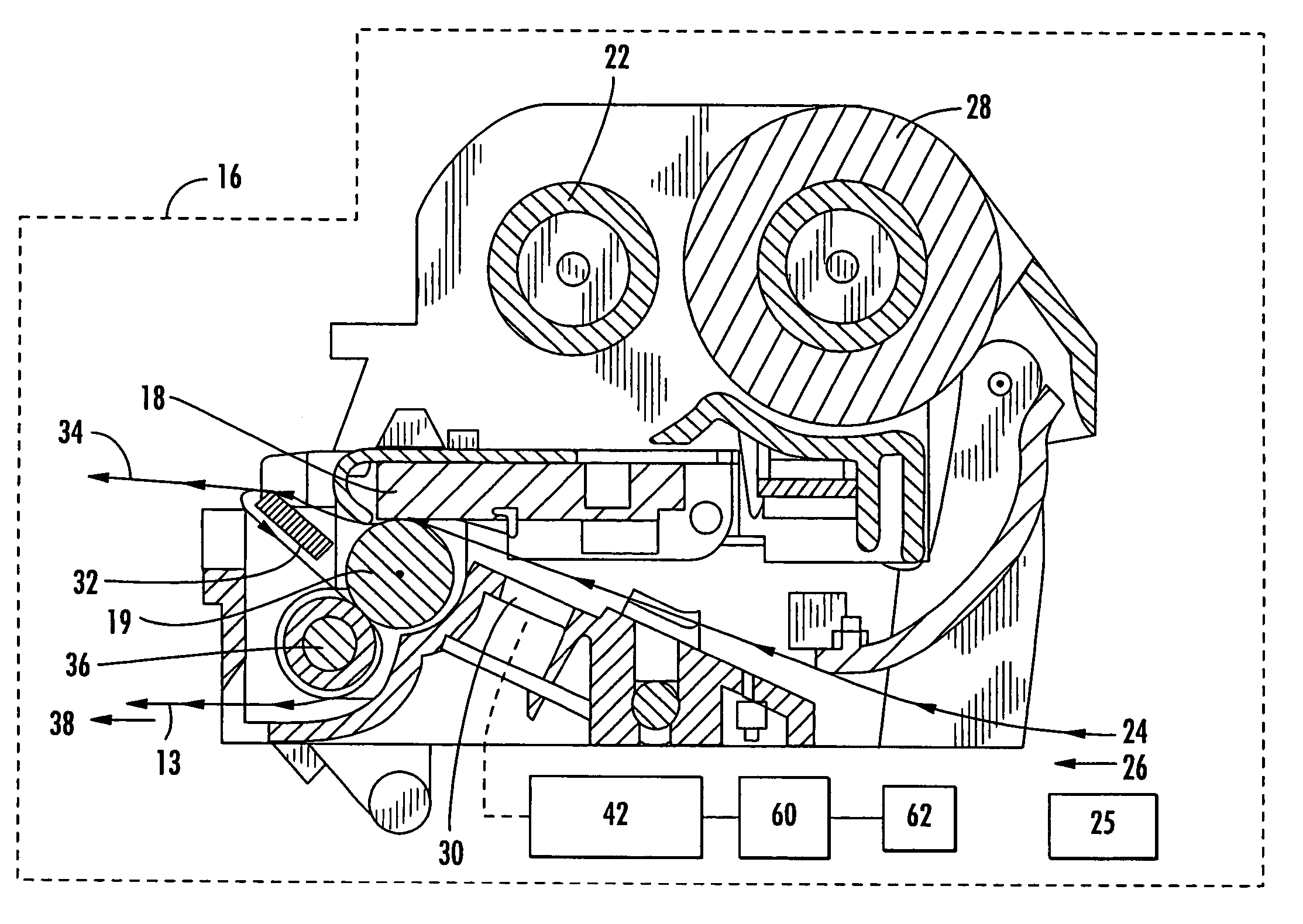
[0035]The present invention addresses the above needs and achieves other advantages by providing a calibration apparatus for determining a location of a transponder supported by a printer media. The calibration apparatus uses a transceiver to attempt to read, write or otherwise communicate with the transponder. Controller logic of the calibration apparatus uses successful and unsuccessful attempts to communicate to determine the location of the transponder. For example, the controller may be configured to move the media in increments, each of the increments being associated with a successful or unsuccessful attempt to communicate with the transponder. The successful attempts, and their relative media positions, are correlated with the position of the transponder. As another example, the controller may be configured to use different power levels for the transceiver and one or more antenna / couplers to determine which power levels are required to successfully communicate with the trans...


PUM


Abstract

A calibration apparatus for determining a location of a transponder supported by a printer media. The calibration apparatus uses a transceiver to attempt to read, write or otherwise communicate with the transponder. Controller logic of the calibration apparatus uses successful and unsuccessful attempts to communicate to determine the location of the transponder. For example, the controller may be configured to move the media in increments, each of the increments associated with a successful or unsuccessful attempt to communicate with the transponder. The successful attempts, and their relative media positions, are correlated with the position of the transponder. Also, the controller may be configured to use different power levels for the transceiver and its one or more couplers to determine which power levels are required to successfully communicate with the transponder. These power levels are correlated with characteristics of the performance of the transponder to determine its distance from the antenna / coupler.

Description

CROSS-REFERENCE TO RELATED APPLICATIONS BACKGROUND OF THE INVENTION[0001]1. Field of the Invention[0002]The present invention is related to dispensing of printer media with radio frequency identification (RFID) tags and, more particularly, to printing on printer media with the RFID tags in combination with writing to, and reading from, the RFID tags.[0003]2. Description of Related Art[0004]UHF radio frequency identification (RFID) technology allows wireless data acquisition and or transmission from and or to active (battery powered) or passive transponders using a backscatter technique. To communicate with, i.e., “read” from and or “write” commands and / or data to a transponder, the transponder is exposed to an RF electromagnetic field by the transceiver that couples with and energizes (if passive) the transponder through electromagnetic induction and transfers commands and data using a predefined “air interface” RF signaling protocol.[0005]When multiple passive transponders are with...

Claims


Application Information

Patent Timeline
Patent Type & Authority Patents(United States)
IPC IPC(8): G08B13/14
CPCG06K7/0008G06K17/00G06K17/0025G06K2017/0083G06K2017/0041
Inventor BROWN, ANTHONY R.TORCHALSKI, KARLSHUFF, WILLIAMREAM, MATTBORISOV, EUGENE
Owner ZEBRA TECH CORP
Why Eureka
Try Eureka