Method and apparatus for mounting rear seat entertainment device

a rear seat and entertainment device technology, applied in the direction of chair, furniture parts, machine supports, etc., can solve the problems of difficult or complicated mounting of the entertainment device, the color and texture of the headrest often do not match with the intended car seat, and the headrest is massively changed, so as to achieve quick and easy mounting, improve the safety of the vehicle, and achieve the effect of optimum viewing angl

Active Publication Date: 2007-04-10
ALPINE ELECTRONICS INC
View PDF18 Cites 52 Cited by
  • Summary
  • Abstract
  • Description
  • Claims
  • Application Information

AI Technical Summary

Benefits of technology

[0009]It is, therefore, an object of the present invention to provide a method and apparatus for mounting a rear seat entertainment display securely without affecting the height adjustment of the headrest.
[0010]It is another object of the present invention to provide a method and apparatus for mounting a rear seat entertainment device on a front seat or a middle seat of a vehicle quickly and easily without increasing the cost.
[0011]It is a further object of the present invention to provide a method and apparatus for mounting a rear seat entertainment device on a front seat or a middle seat of a vehicle without adversely affecting the safety of the vehicle.
[0019]Another aspect of the present invention is an apparatus for mounting a rear seat entertainment device on a seat of a vehicle for implementing the various steps defined in the mounting method of the present invention noted above. The mounting apparatus allows a user to attach the rear seat entertainment device easily and quickly to a front seat or a middle seat of a vehicle without affecting the height adjustment of a headrest.
[0020]According to the present invention, the rear seat entertainment device can be mounted on the front seat or middle seat of the vehicle quickly and easily without increasing the cost or adversely affecting the safety of the vehicle. The method and apparatus of the present invention for mounting the rear seat entertainment device eliminates the need of gauging out the back of the seat or the headrest. Moreover, the position of the entertainment device will not be changed when the front seat passenger adjusts the height of the headrest. The method and apparatus of mounting the entertainment device in the present invention allows optimum viewing angle even when the user changes the height of the head rest.

Problems solved by technology

First, mounting the entertainment device is difficult or complicated because the back of the head rest 85 must be gauged out.
It requires massive changes of the headrest 85 that necessitate specialized tools and components to complete the job.
However, the colors and textures of the headrest often do not match to those in the intended car seat.
Providing suitable headrests with a display to vehicles in the market is costly due to the variety of vehicles and their colors.
This can lead to an inappropriate viewing angle, which may discomfort the rear or middle seat passenger.
More seriously, the headrest may not function properly when an accident occurs because the inner original materials thereof have to be removed.
Although this placement can avoid the interference arising from the adjustment of the headrest, the position of the display tends to be too low and therefore an optimum viewing angle is difficult to attain.
Moreover, mounting the entertainment device is difficult or involves a substantial amount of work because the back of the front seat must be gauged out.
It requires massive works by using special tools to make the placement hole and installing the entertainment device therein, resulting in high cost.
Further, if a second buyer of the vehicle does not like the location of the entertainment device, the whole seat may have to be replaced.

Method used


Image

  • Method and apparatus for mounting rear seat entertainment device
  • Method and apparatus for mounting rear seat entertainment device
  • Method and apparatus for mounting rear seat entertainment device

Examples


first embodiment

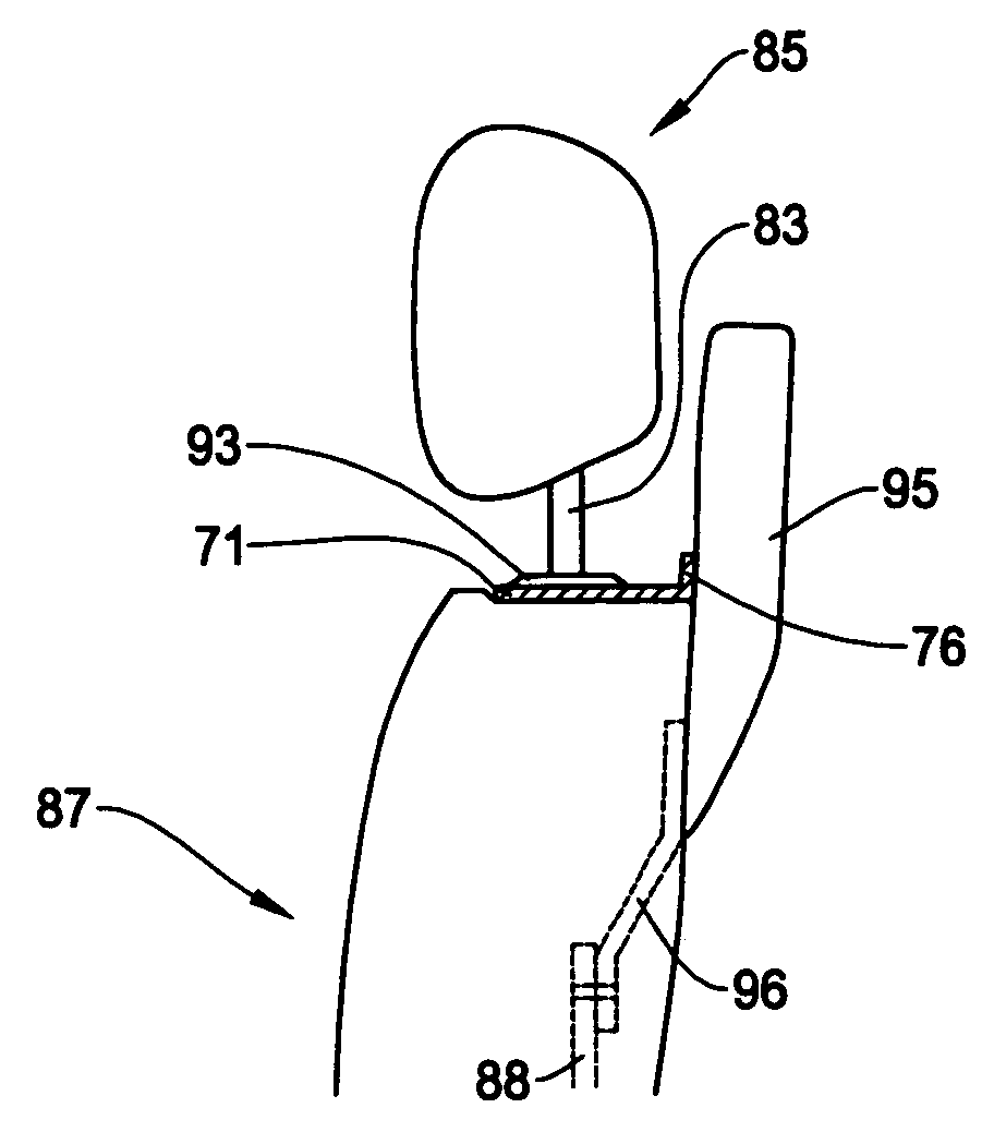
[0038]FIG. 5 shows a bracket 71 incorporated in the present invention for mounting a RSE device 95 on the front seat 87. The bracket 71 comprises a hook (attachment) portion 77, a plate portion 75 and a mounting wall 76 (FIG. 6). The hook portion 77 fits with the support tube flanges 93 on the top of the seat front 87, thereby mounting a RSE device on the top of the front seat 87. In this embodiment, the attachment portion 77 has a hook-like shape that encircle the support tubes 91 as will be explained later in more detail. The attachment portion 77 has a J-shape to form a round area (opening) 73 to allow easy installation of the bracket 71 due to its opening at one side as will be explained later in detail.

[0039]FIG. 6 is a perspective view showing the bracket 71 of FIG. 5 in the present invention. The bracket 71 has a mounting wall 76 which is in a predetermined angle, for example, perpendicular to the plate portion 75. This mounting wall 76 has fixing means such as screw holes 79...

fourth embodiment

[0055]The bracket of the present invention can be constructed by combining separate components. Such a configuration achieves flexibility for mounting the RSE device for various types of vehicle by changing the components. FIGS. 12A and 12B show the present invention incorporating the separate components where FIG. 12A is a plan view and FIG. 12B is a side view of the bracket. In this example, separate hinges are used for the attachment portion of the bracket.

[0056]More specifically, a bracket 371 has attachment holes (slits) 361 that receive hinges 347. Preferably, the attachment holes 361 have a size slightly larger than the cross sectional size of the hinges 347. The hinges 347 have a U-shape in plan view for receiving the support tubes 91 and have a step like shape in side view for connection with the bracket 371. The structure of the bracket 371 and hinges 347 is useful to cover a variety of sizes and shapes of the support tubes 91 by changing the hinges. Thus, when being attac...

fifth embodiment

[0058]FIGS. 13A and 13B show the present invention where FIG. 13A is a plan view and FIG. 13B is a side view of the bracket. This example is similar to that of FIGS. 12A and 12B by incorporating the separate hinges while the method for connecting the hinges to the bracket is different from one another. Such a configuration achieves flexibility for mounting the RSE device for various types of vehicle by preparing different sizes and shapes of the hinges.

[0059]More specifically, a bracket 471 has attachment holes 447 for connecting hinges 449 with use of fastening means such as screws 448. The hinges 449 have a U-shape in plan view for receiving the support tubes 91 and have screw holes corresponding to the attachment holes 447 on the bracket 471. Thus, the hinges 449 are connected to the bracket 471 through the screws 448. The structure of the bracket 471 and the hinges 449 is useful to cover a variety of sizes and shapes of the support tubes 91 by changing the different size and sha...


PUM


Abstract

A method and apparatus for mounting a rear seat entertainment device easily and quickly on a seat of a vehicle without affecting the height adjustment of a headrest. The method includes the steps of preparing a bracket having an attachment portion for attachment with the seat and a mounting wall for attachment with a rear seat entertainment device, shifting a headrest upwardly to expose a headrest support tube and a flange of the support tube, placing the attachment portion of the bracket between the flange and a top surface of the seat in such a way that an opening of the attachment portion surrounds the support tube, attaching the rear seat entertainment device to the mounting wall of the bracket, and fixedly attaching a lower part of the rear seat entertainment device to the back of the seat.

Description

FIELD OF THE INVENTION[0001]This invention relates to a method and apparatus for mounting a rear seat entertainment device on a back of a seat. More particularly, this invention relates to a method and apparatus for mounting a rear seat entertainment device on a front seat or a middle seat of a vehicle with use of a support tube of a headrest to securely attach the entertainment device without affecting the adjustability of the headrest.BACKGROUND OF THE INVENTION[0002]As the technologies for display devices, speakers, and DVD systems advance, the demand for mounting these audio and video devices on a vehicle becomes higher and higher for enjoyment of music, moves, etc., in the vehicle. Normally, such an audio and video device (rear seat entertainment device) comprises a display unit or monitor, a speaker, and a playback device such as a videocassette player or a DVD player. Typically, such an audio and video device is mounted on a back of a front seat or middle seat of the vehicle ...

Claims


Application Information

Patent Timeline
Patent Type & Authority Patents(United States)
IPC IPC(8): A47C7/62B60N2/809B60N2/879
CPCB60N2/4876B60R11/0235B60R2011/0017B60R2011/0059B60R2011/0071Y10S248/917B60N2/879B60N2/809
Inventor CILLUFFO, JOSEPHBARTLE, ALDEN
Owner ALPINE ELECTRONICS INC
Why Eureka
Try Eureka