Display swivel

a technology of display swivel and rotating portion, which is applied in the direction of suspension devices, rod connections, television systems, etc., can solve the problems of loose display on the display swivel, inappropriate use of conventional cathode ray tube displays in multimedia applications, etc., to reduce friction of rotating the rotational portion, rotate smoother, and rotate the rotational portion.

Inactive Publication Date: 2007-06-05
QUANTA COMPUTER INC
View PDF6 Cites 23 Cited by
  • Summary
  • Abstract
  • Description
  • Claims
  • Application Information

AI Technical Summary

Benefits of technology

[0006]It is an object of the present invention to provide a display swivel with fixing washers that effectively and safely configures a fixing device of the display swivel thereon.
[0007]It is another object of the present invention to provide a display swivel with a fixed lubricating washer for rotating the display swivel smoothly.
[0008]It is further object of the present invention to provide a display swivel utilizing a rotational shaft inserted into a rotational ring and forming two sliding surfaces on both sides of the rotational ring to provide a smooth, safe rotation for the swivel.
[0010]The rotational portion further includes a rotational disc. The rotational disc and the pedestal construct a first sliding surface therebetween. The first sliding surface further has a lubricant thereon for reducing a rotation friction of the display swivel and can include a plurality of hollows to store the lubricant therein. A second sliding surface is constructed between the rotational shaft washer and the lubricating washer. In the same manner, the second sliding surface can include a plurality of hollows or holes to store the lubricant therein. The first sliding surface and the second sliding surface are respectively disposed on both sides of the rotational ring to reduce the friction for rotating the rotational portion.
[0013]The display swivel according to the present invention utilizes the rotational shaft washer to prevent the fixing device of the display swivel from falling off, and the fixing device of the display swivel can be therefore firmly secured on the rotational shaft. The display swivel according to the present invention further utilizes the first sliding surface and the second sliding surface disposed on both sides of the rotational ring to reduce a friction for rotating the rotational portion so that the rotational portion can rotate smoother. The angle restrictor and the angle-restricting trench coupling together can further provide a suitable angle protection for the display swivel.

Problems solved by technology

Conventional cathode ray tube (CRT) displays are inappropriate for use in multimedia applications because of their large volume.
Although a conventional display swivel normally provides a horizontal rotation function, the display may sometimes become loose on the display swivel due to looseness of fixing devices caused by frequent rotations.
More seriously, the display may fall from the swivel so as to damage the display.

Method used


Image

  • Display swivel
  • Display swivel

Examples


Embodiment Construction

[0016]The following description is of the best presently contemplated mode of carrying out the present invention. This description is not to be taken in a limiting sense but is made merely for the purpose of describing the general principles of the invention. The scope of the invention should be determined by referencing the appended claims.

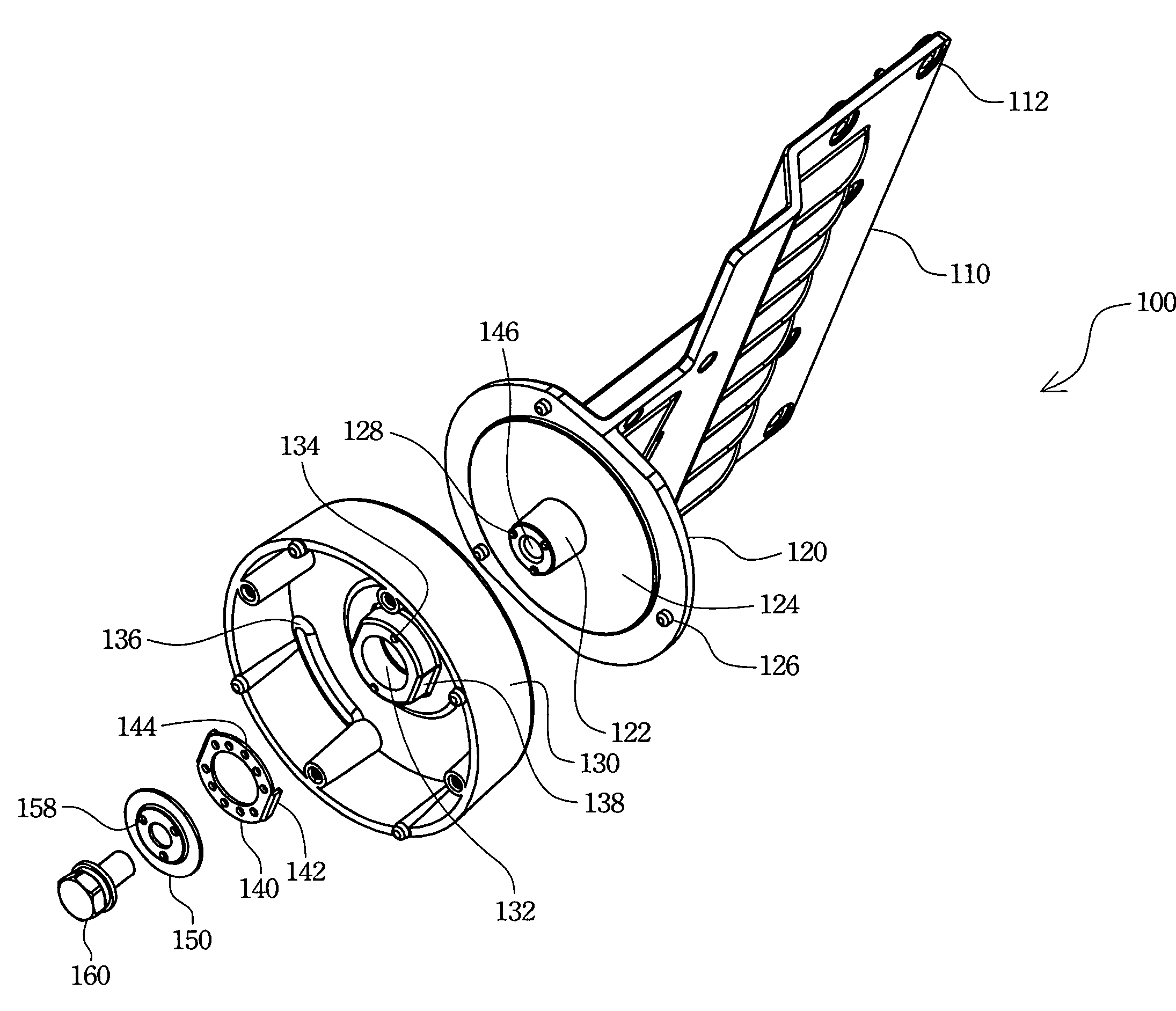
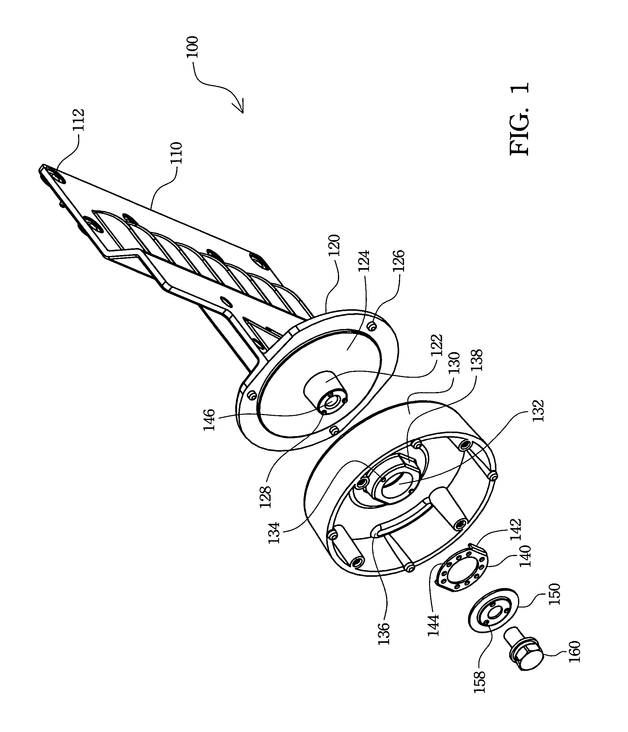
[0017]FIG. 1 is a preferred embodiment of a display swivel according to the present invention. Referring to FIG. 1, the display swivel 100 includes a display supporting plate 110, a rotational portion 120, and a pedestal 130. The display supporting plate 110 is fixed to the rotational portion 120 for rotating on the pedestal 130. A flat display panel is fixed on the display supporting plate 110 by way of display fixing hole 112 and corresponding fixing devices (not shown) to increase an effective fixing area between the flat display panel and the display swivel 100.

[0018]A rotational shaft 122 of the rotational portion 120 rotatably couples to a ...


PUM


Abstract

A display swivel is described. The display swivel has a rotational portion, a pedestal, a fixed washer, a lubricating washer, and a fixing device. The rotational portion utilizes a rotational shaft to couple to a rotational ring of the pedestal. The fixed washer is fixed on the rotational shaft, and the lubricating washer is fixed on the rotational ring and is configured between the fixed washer and the rotational ring. The fixing device couples to the rotational shaft through central holes of the fixed washer and the lubricating washer.

Description

RELATED APPLICATIONS[0001]The present application is based on, and claims priority from, Taiwan Application Serial Number 93209789, filed Jun. 21, 2004, the disclosure of which is hereby incorporated by reference herein in its entirety.FIELD OF THE INVENTION [0002]The present invention generally relates to a display swivel. More particular, the present invention relates to a flat panel display swivel.BACKGROUND OF THE INVENTION [0003]Conventional cathode ray tube (CRT) displays are inappropriate for use in multimedia applications because of their large volume. Therefore, many flat panel display techniques such as liquid crystal display (LCD), plasma display panel (PDP), and field emission display (FED) have been recently developed. These display techniques can manufacture a thin, light, short and small display, and thus these techniques are and will be the mainstream technology.[0004]Flat panel displays possess advantages of high quality, small volume, and light weight, and are wide...

Claims


Application Information

Patent Timeline
Patent Type & Authority Patents(United States)
IPC IPC(8): E04G3/00A47H1/10F16C23/04F16C33/10F16M11/08H04N5/655
CPCF16C33/102F16C33/103F16M11/06F16M11/08Y10T403/32581Y10S248/921Y10T403/32065
Inventor LIN, CHIH-CHIANG
Owner QUANTA COMPUTER INC
Why Eureka
Try Eureka