Oriented PIFA-type device and method of use for reducing RF interference

a pifa-type device and interference reduction technology, applied in the structural form of radiating elements, resonance antennas, antenna earthings, etc., can solve the problems of excessive audio noise being presented to the user, user's hearing aid audio noise may be generated, etc., to promote a reduction of sar for a pwd, reduce radiation, and prolong transmit/receive the effect of rang

Inactive Publication Date: 2007-06-12
AERIUS INT
View PDF15 Cites 67 Cited by
  • Summary
  • Abstract
  • Description
  • Claims
  • Application Information

AI Technical Summary

Benefits of technology

[0012]The device of the present invention greatly reduces radiation directed toward a user's hand and head during device operation. As a result, the device promotes a reduction of the SAR for a PWD. Other benefits include longer transmit / receive range, lower transmit power, and longer battery life. Yet another benefit is the reduction in PWD generated noise in a user's hearing aid.
[0013]A device according to the present invention may include a PWD implemented for operation over single or multiple frequency-band. An antenna may be incorporated within a PWD at the time of manufacture, or may be provided as an accessory or after market item to be added to existing PWDs having an external antenna port. The latter feature is particularly useful, in that existing PWDs can be retrofitted to achieve the benefits of the antenna of the present invention, including elimination of hearing aid noise and very low SAR. The antenna of the present invention is suitable for high-volume, low cost manufacturing. The antenna / PWD combination, whether an aftermarket or original equipment item, may be placed in a leather or plastic case, such that the antenna side of the PWD is facing away from the body. This provides a further advantage with respect to SAR, when the PWD is stored via a belt clip when in receive-only mode.
[0016]the elimination (or substantial reduction) of audio noise in hearing aids caused by close proximity to transmitting PWDs, particularly PWDs operating in one or more frequency bands, enabling use of hearing aids in close proximity to such PWDs;
[0022]the provision of an antenna promoting increased PWD battery life by reducing commanded RF power;

Problems solved by technology

Prior art antennas for PWDs may cause audio noise in a hearing aid of the user.
RF noise is induced in the hearing aid by the field 408, resulting in excessive audio noise being presented to the user.
However, even at this level audio noise may be generated in a user's hearing aid by operation of PWD 444.
Another limitation of the PIFA is its relatively low front-to-back ratio.
This type of antenna provides some reduction in SAR, but has limited ability to reduce hearing aid noise from a digital PWD.
Despite all of the desirable properties of a PIFA, the PIFA has the limitation of a rather large physical size for practical application.
With the rapidly advancing size miniaturization of the radio communication devices, the space requirement of a conventional PIFA is a severe limitation for its practical utility.

Method used


Image

  • Oriented PIFA-type device and method of use for reducing RF interference
  • Oriented PIFA-type device and method of use for reducing RF interference
  • Oriented PIFA-type device and method of use for reducing RF interference

Examples


Embodiment Construction

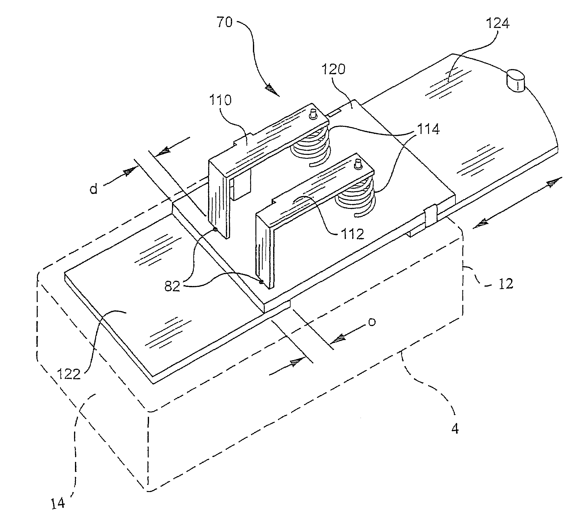
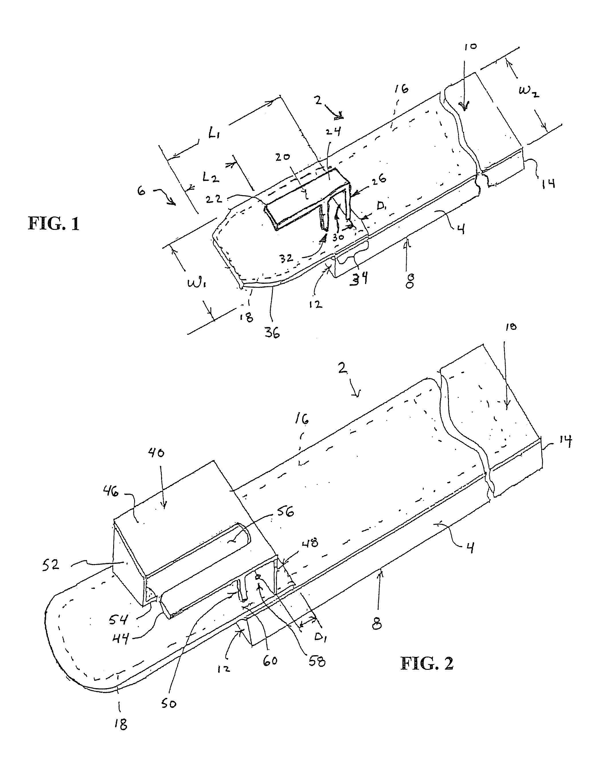
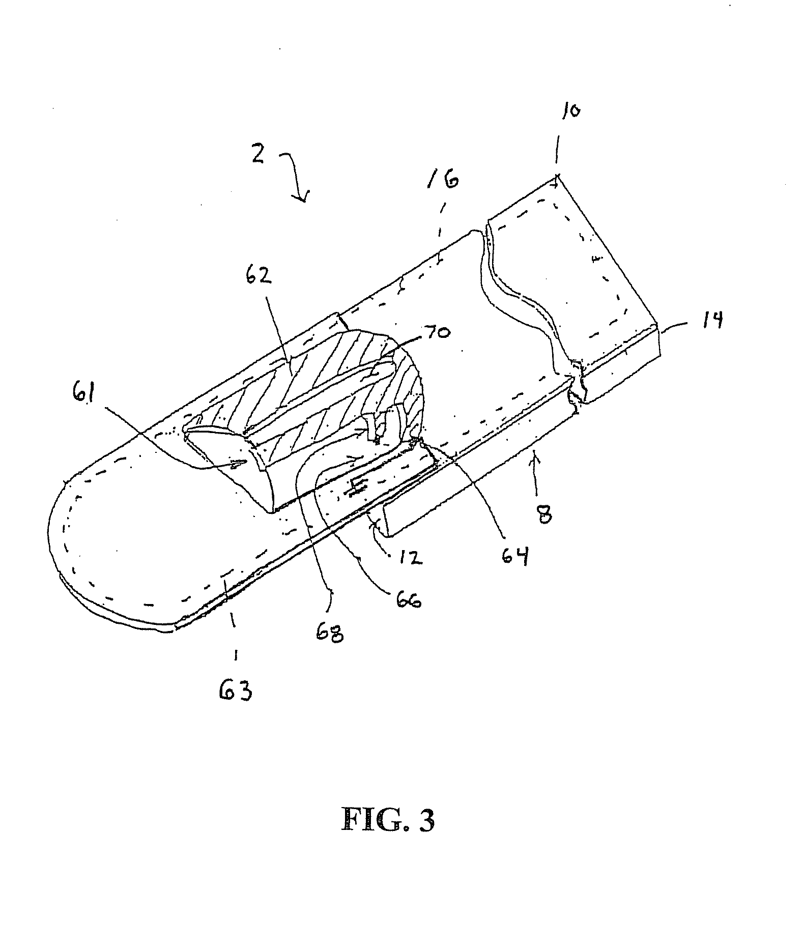
[0044]Referring to FIGS. 1 through 3, a device according to one embodiment of the present invention is indicated as numeral 2. Device 2 includes a portable wireless device “PWD”4 and a PIFA antenna structure 6. Relative to a user, in operation PWD 4 includes a front side 8 which is nearer to the user than a back side 10. PWD 4 has a top 12 and a bottom 14. In operation, bottom 14 is between top 12 and the ground surface upon which the user is positioned. PWD 4 is generally aligned in operation so that its top 12 is above a user's hand which grasps the PWD. PWD 4 includes a ground plane 16, typically a conductive plane within a printed wiring board upon which electronic components are secured.

[0045]Antenna structure 6 includes a ground plane conductor element 18 and a configured conductive radiating element 20. Element 20 may include a plurality of planar surfaces or may be configured to have some curvature or other shape. Element 20 may be formed as a metal part or may be a plating ...


PUM


Abstract

An oriented PIFA-type apparatus for reducing hearing aid radio frequency (RF) interference including a directional multi-band and / or single band antenna for use with PWDs such as digital cellphones is disclosed. The apparatus greatly reduces or eliminates the audio noise induced in hearing aids by the PWDs and allows operation of a hearing aid during PWD operation. In operation, the apparatus may be provided on the PWD side away from the user's head. The apparatus may be integrated into the PWB during its manufacture or provided as an after market assembly for a PWD that has a port for connection of an external antenna. The apparatus provides for improved front-to-back ratio as compared to antennas currently in use on PWD's, and therefore also reduces SAR (specific absorption rate), the level of RF energy received into the head by a PWD.

Description

[0001]This is a continuation-in-part application of application Ser. No. 10 / 262,447, filed Sep. 30, 2002 now U.S. Pat. No. 6,639,564, which claims benefit of provisional Application No. 60 / 357,162, filed Feb. 13, 2002.RELATED APPLICATIONS[0002]PCT Patent Application US / 03 / 04230, filed Feb. 12, 2003,[0003]U.S. patent application Ser. No. 10 / 262,447, filed Sep. 30, 2002, and[0004]U.S. Patent Application Ser. No. 60 / 357,162, filed Feb. 13, 2002.FIELD OF THE INVENTION[0005]The present invention relates to a portable wireless communications device. More particularly, the present invention relates to an oriented PIFA assembly and ground conductor for reducing the specific absorption rate (SAR) of the associated device during operation.BACKGROUND[0006]SAR (specific absorption rate) for users of portable wireless devices (PWDs) is a matter of increasing concern. RF radiation to the user's head results from the free-space generally omnidirectional radiation pattern of typical current PWD ant...

Claims


Application Information

Patent Timeline
Patent Type & Authority Patents(United States)
IPC IPC(8): H01Q1/24
CPCH01Q1/243H01Q9/0421
Inventor JOHNSON, GREG
Owner AERIUS INT
Why Eureka
Try Eureka