Identifying remote radio units in a communication system

a technology of communication system and remote radio unit, applied in the field of communication system, can solve the problems of insufficient accuracy of location information obtainable for user equipment relative to the base station in certain cases, and it is not possible to determine from which of the remote radio units a signal has been received

Inactive Publication Date: 2007-10-23
NOKIA SOLUTIONS & NETWORKS OY
View PDF3 Cites 96 Cited by
  • Summary
  • Abstract
  • Description
  • Claims
  • Application Information

AI Technical Summary

Problems solved by technology

Therefore, it may not be possible to determine from which of the remote radio units a signal has been received and thus which remote radio unit is closest to the mobile user.
As a base station provided with remote radio units may cover a large area, the accuracy of the location information obtainable for a user equipment relative to the base station may in certain cases be insufficient, for example for commercial or emergency needs.

Method used


Image

  • Identifying remote radio units in a communication system
  • Identifying remote radio units in a communication system
  • Identifying remote radio units in a communication system

Examples


Embodiment Construction

[0023]Some preferred embodiments of the invention are described in the following. It is to be noted that the invention is not limited to these exemplifying embodiments.

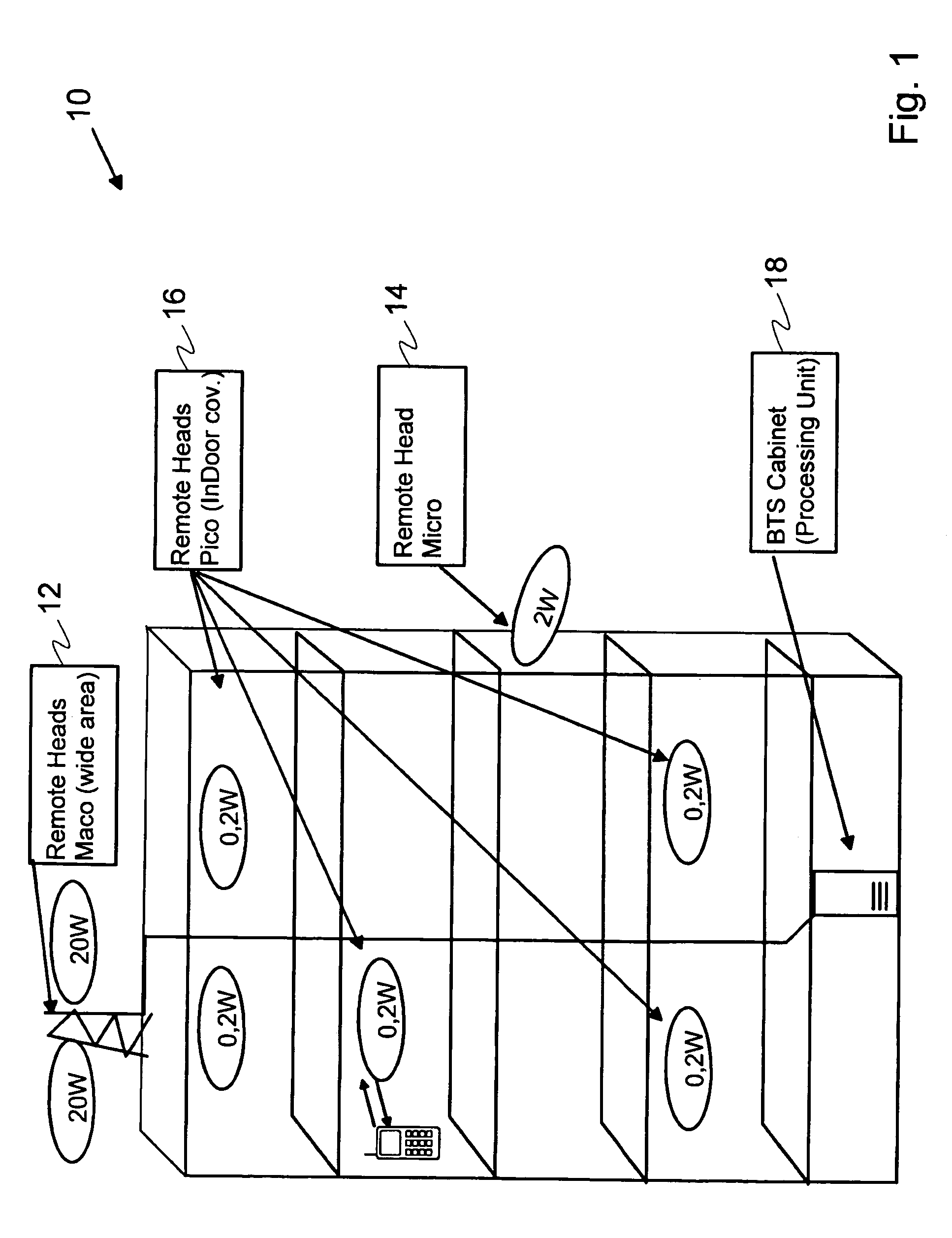
[0024]FIG. 1 shows an example of a distributed base station system 10 provided in a building. Multiple remote radio units 12, 14, 16, such as transceivers (TRXs), other radio units or distributed antenna system, are combined to one single base station and connected to a common base station processor unit 18 in a base station cabinet. As an example, the remote radio units in a distributed base station system may include relatively powerful wide area coverage heads (Maco) 12, less powerful micro heads 14 and low power indoor coverage heads (Pico) 16. User equipment 20 is shown to be connected with the base station system 10 over a wireless interface, such as a radio path.

[0025]Using prior art systems described above, the location of a user could be determined as being somewhere in or in the proximity of the building. Em...


PUM


Abstract

A method for identifying a remote radio unit in a communication system comprises a plurality of remote radio units communicating with a central unit and pattern providing means for providing information about dedicated gain change patterns of the remote radio units. The method comprises receiving a signal from a station by a remote radio unit of the plurality of remote radio units. The method also includes changing the gain of at least one remote radio unit according to a dedicated gain change pattern of the at least one remote radio unit. The method also includes detecting a gain change pattern for the received signal and identifying the remote radio unit by comparing the detected gain change pattern with information about dedicated gain change patterns of the remote radio units provided by the pattern providing means. An example may be locating a station, such as a user equipment, in a distributed radio system.

Description

FIELD OF THE INVENTION[0001]The invention relates to communication systems, and more particularly to identifying remote radio units in a communication system, such as a distributed communication system.BACKGROUND OF THE INVENTION[0002]Mobile communication systems allow mobility for users thereof. A mobile communication system may be provided by a cellular or otherwise wireless communication system using radio frequencies for sending voice or data between stations, such as user equipment (UE) (e.g. mobile stations, MS) and base transceiver stations (BTS), also called base stations. A base station system commonly comprises an antenna connected with appropriate electronics and control devices and so on. The radio frequencies may be divided in channels including traffic channels for voice and data transfer and signal channels for transferring control signals for the purposes of setting up a call or controlling an ongoing connection. Examples of cellular mobile communication systems incl...

Claims


Application Information

Patent Timeline
Patent Type & Authority Patents(United States)
IPC IPC(8): H04Q7/20H04BH04W4/04H04W8/04H04W16/26H04W64/00H04W84/14H04W88/08
CPCH04W64/00H04W4/04H04W8/04H04W88/085H04W84/14H04W16/26
Inventor SCHECK, HANS-OTTO
Owner NOKIA SOLUTIONS & NETWORKS OY
Why Eureka
Try Eureka