Bumper structure

a bumper and bumper technology, applied in the direction of bumpers, transportation and packaging, vehicle safety arrangments, etc., can solve the problem of the hole wall pressure drop in the overlap zon

Inactive Publication Date: 2007-11-06
BENTELER AUTOMOBILTECHNIK GMBH
View PDF3 Cites 26 Cited by
  • Summary
  • Abstract
  • Description
  • Claims
  • Application Information

AI Technical Summary

Benefits of technology

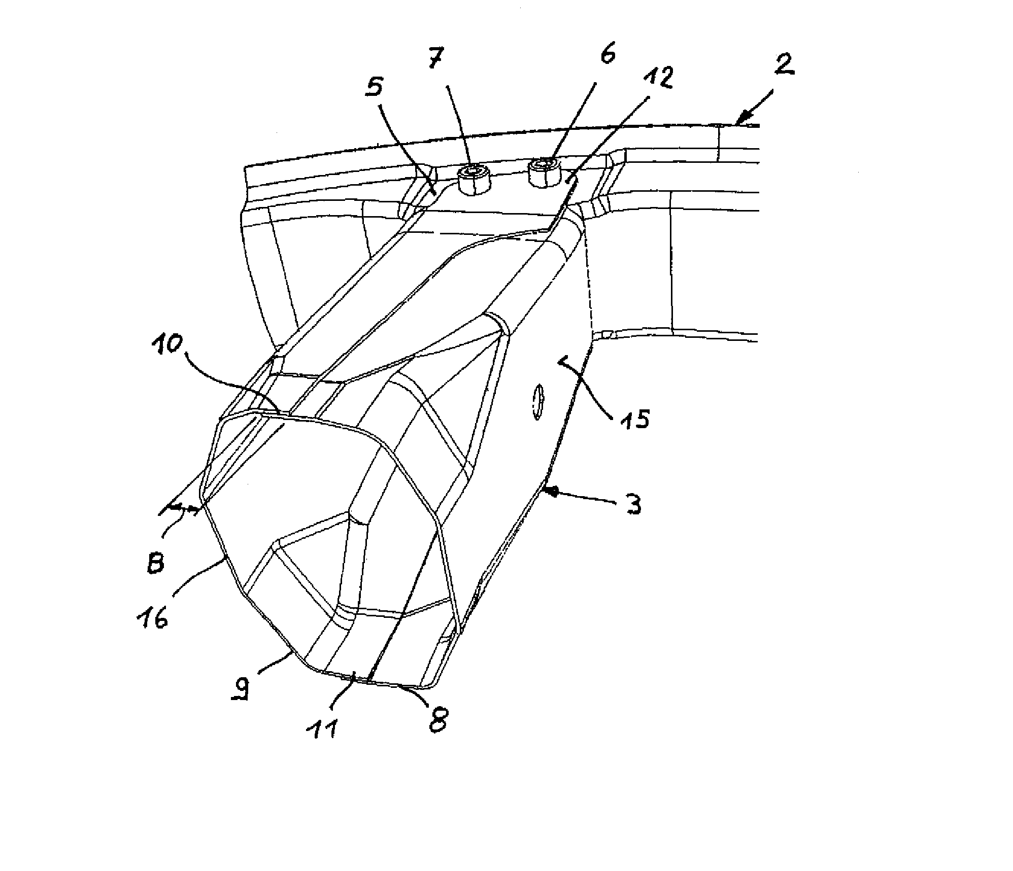
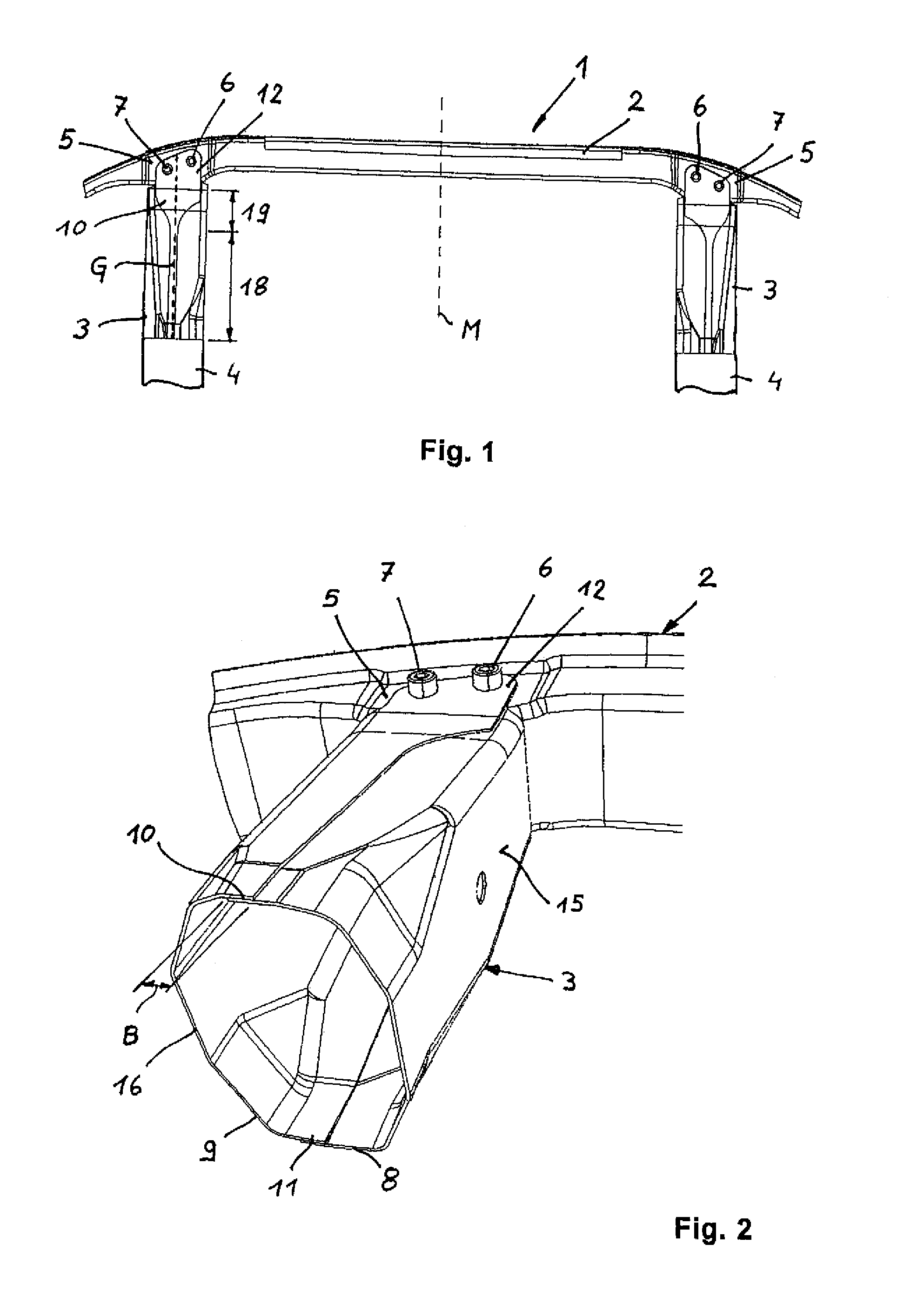
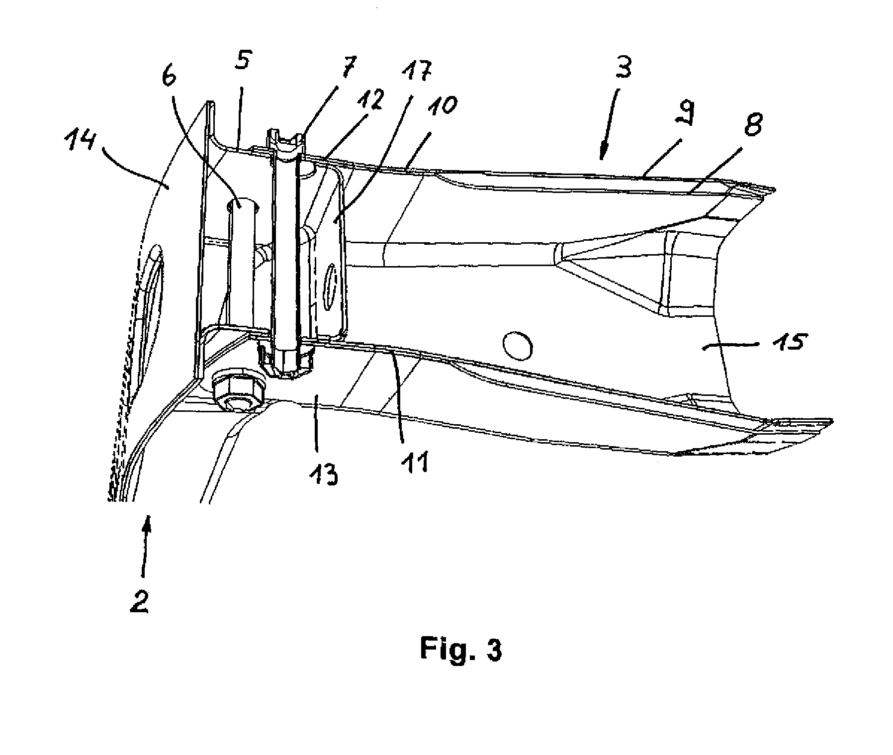
[0009]An essential feature of the present invention is the formation of an overlap, i.e. a doubling of material, in an attachment zone between crash box and the cross member, i.e. area which is traversed by the bolt. As a result of the material doubling, impact forces that are introduced by the bolted connection into the crash box are transmitted directly and simultaneously via the wall of the hole into the shells. This has the advantage of spreading the load in the area traversed by the bolt to both shells so that deformation of the shells is encountered only when the shells are subjected to a much greater force. In addition, the material doubling also results in a decrease of the pressure on the wall of the hole in the overlap zone.
[0010]The invention makes it now possible to manufacture crash boxes of relatively thin-walled metal sheets which have a sufficient wall thickness in their attachment zone to the cross member as a consequence of the overlapping zones so that introduced stress can be transferred into the crash box. Thus, the crash box can be manufactured in a simple manner and of lightweight construction while still exhibiting high stability in the attachment zone of the cross member.
[0011]A crash box configured in accordance with the invention is also of advantage when, in the event of a collision, the crash-distal crash box has to absorb impact forces that have been transmitted via the cross member but still should remain undamaged. In this case, it is important that no damage is encountered in the attachment zones between the cross member and the crash box. This can be attained by a doubling of material in the overlap zone and the resultant decrease in pressure to which the wall of the hole is subjected.
[0012]The overlap zones can be configured in the form of opposing flanges which embrace an attachment zone of the cross member. The flanges are easy to produce through use of a suitable sheet-metal blank before shaping the blank to the sheet-metal shells. Suitably, the shells overlap one another entirely in an area of the flanges. As a result, a substantially same stress pattern can be realized for both shells in the area of the flanges.
[0013]According to another feature of the present invention, the overlap zone defines a width which is measured transversely to a travel direction of the motor vehicle and varies along the length extension of the crash box. Currently preferred is an increase in width of the overlap zone of the shells from the end of the side rail in the direction to the cross member. The width of the overlap zone in the area of the cross member may hereby be at least twice the width of the overlap zone in an area of the side rail. The considerable change in width enables a stress pattern that is substantially even and an optimal force introduction into the crash box constructed as hollow body. Despite the change in width along the length, it is, of course, also conceivable to maintain the width of the overlap zone constant in a length section disposed adjacent to the side rail and to provide a transition, extending from the length section to the flanges, wherein a width of the transition continuously increases to a width of the flanges. The length section may hereby have a length which is greater than a length of the transition. As a result, the change in width is substantial in the shorter transition zone.
[0015]The course of the straight line is determined by the position of the overlap zones. Suitably, the straight line extends up to the flanges and extends in an area of the flanges between the bolts disposed in parallel spaced-apart relationship so that one bolt is positioned on one side of the straight line and the other bolt is positioned on the other side of the straight line. A connection of the flanges through material union only in the area of the straight line is sufficient when the bolted connection ensures enough integrity of the remaining overlap zone. As the bolted connection normally brace the flanges against the cross member, the overlap zones rest firmly upon the attachment zone of the cross member so that the need for a large-surface welding of the flanges, e.g. welding along the edges, is eliminated.

Problems solved by technology

In addition, the material doubling also results in a decrease of the pressure on the wall of the hole in the overlap zone.

Method used


Image

  • Bumper structure
  • Bumper structure
  • Bumper structure

Examples


Embodiment Construction

[0020]Throughout all the Figures, same or corresponding elements are generally indicated by same reference numerals. These depicted embodiments are to be understood as illustrative of the invention and not as limiting in any way. It should also be understood that the figures are not necessarily to scale and that the embodiments are sometimes illustrated by graphic symbols, phantom lines, diagrammatic representations and fragmentary views. In certain instances, details which are not necessary for an understanding of the present invention or which render other details difficult to perceive may have been omitted.

[0021]This is one of two applications both filed on the same day. Both applications deal with related inventions. They are commonly owned and have the same inventive entity. Both applications are unique, but incorporate the other by reference. Accordingly, the following U.S. patent application is hereby expressly incorporated by reference: “Bumper Structure”.

[0022]Turning now t...


PUM


Abstract

A bumper structure for the front and rear area of a motor vehicle includes a bumper cross member and a crash box which is placed between the cross member and an end of a side rail. The crash box is configured in the form of a hollow body made of two sheet-metal shells which overlap one another in an overlap zone and are interconnected, at least in sections thereof, through material union. The cross member is detachably secured to the crash box by a bolted connection having at least one bolt which extends in upright direction of the motor vehicle and is arranged in the overlap zone of the crash box. Force introduction from the cross member into the crash box is hereby improved.

Description

CROSS-REFERENCES TO RELATED APPLICATIONS[0001]This application claims the priority of German Patent Application, Ser. No. 10 2006 013 274.2, filed Mar. 21, 2006, pursuant to 35 U.S.C. 119(a)-(d), the content of which is incorporated herein by reference in its entirety as if fully set forth herein.BACKGROUND OF THE INVENTION[0002]The present invention relates, in general, to a bumper structure for a motor vehicle.[0003]Nothing in the following discussion of the state of the art is to be construed as an admission of prior art.[0004]A bumper structure is mounted to the front or rear of a motor vehicle to convert generated impact energy into deformation work, in the event of a frontal or rear impact with a road user or in the event of a collision with an obstacle, so as to prevent or minimize damage to vehicle components, in particular the chassis, and thus to limit the amount of damage. In addition, a bumper structure is provided to assist in the stiffening of the vehicle chassis. Sinc...

Claims


Application Information

Patent Timeline
Patent Type & Authority Patents(United States)
IPC IPC(8): B60R19/24
CPCB60R19/34B60R19/24
Inventor ARNS, WILHELM
Owner BENTELER AUTOMOBILTECHNIK GMBH
Why Eureka
Try Eureka