Projection display apparatus

a technology of projection display and display screen, which is applied in the direction of television systems, instruments, optical elements, etc., can solve the problems of uncontrolled heterogeneous brightness level over the screen, and achieve the effects of improving brightness, uniform brightness level, and better control of light distribution over the screen

Inactive Publication Date: 2007-11-27
THOMSON LICENSING SA
View PDF13 Cites 0 Cited by
  • Summary
  • Abstract
  • Description
  • Claims
  • Application Information

AI Technical Summary

Benefits of technology

[0005]The invention aims at a solution allowing designers to better control the distribution of light over the screen, for instance to obtain a more uniform brightness level, possibly together with a higher brightness level in the center.
[0011]In order to improve the accuracy of the light distribution control, the light guide has an input face contacting another light guide. Preferably, the other light guide generates a substantially uniform light distribution over the input face.
[0015]In a further possible embodiment, the gradient filter is colored and can therefore compensate for color non-uniformities in the apparatus.

Problems solved by technology

As the transmission factor of the screen depends on the incoming angle of light, as in any optical system, this results in an uncontrolled heterogeneous brightness level over the screen (generally the bottom part is brighter).

Method used


Image

  • Projection display apparatus
  • Projection display apparatus
  • Projection display apparatus

Examples


Embodiment Construction

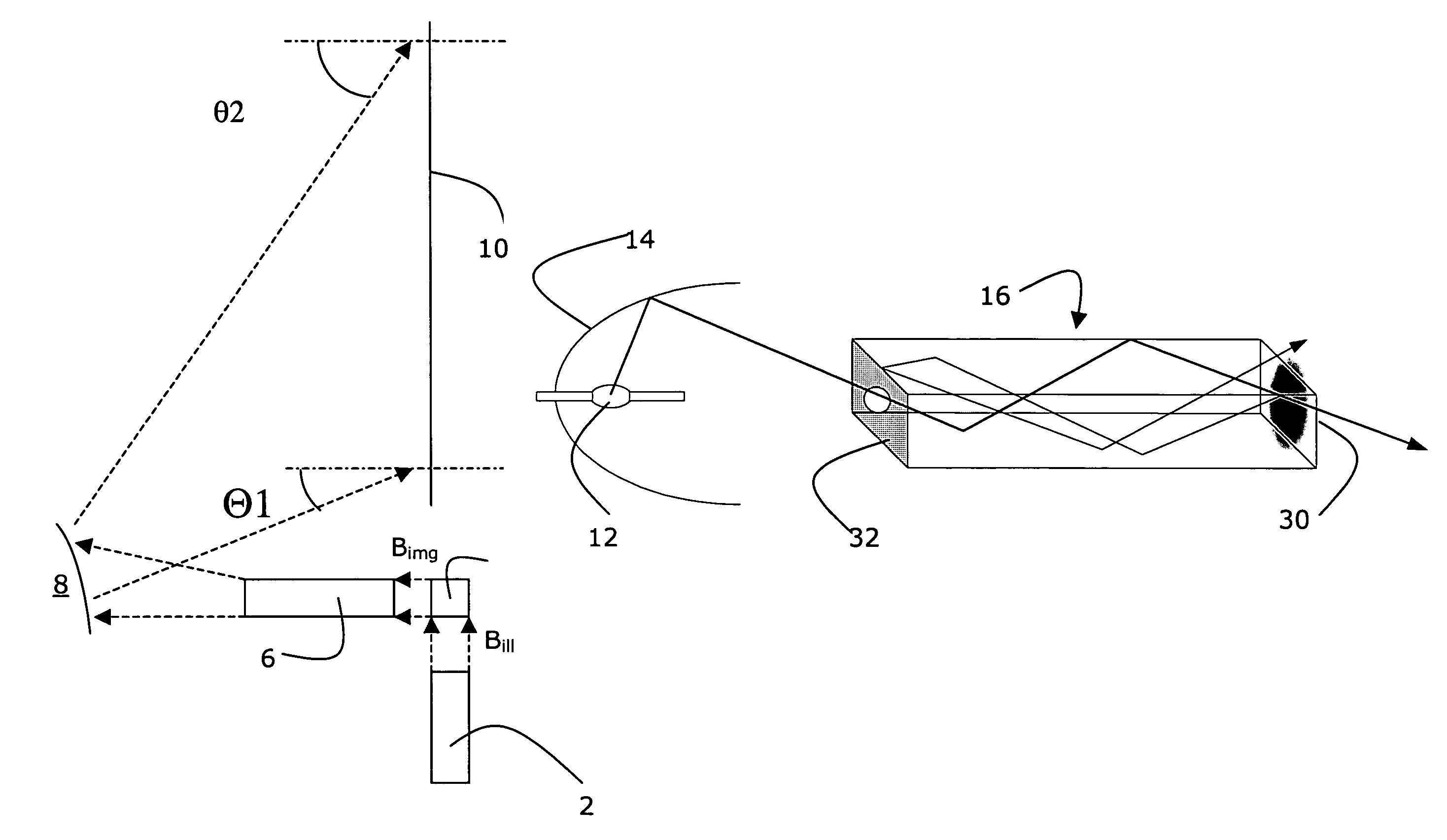
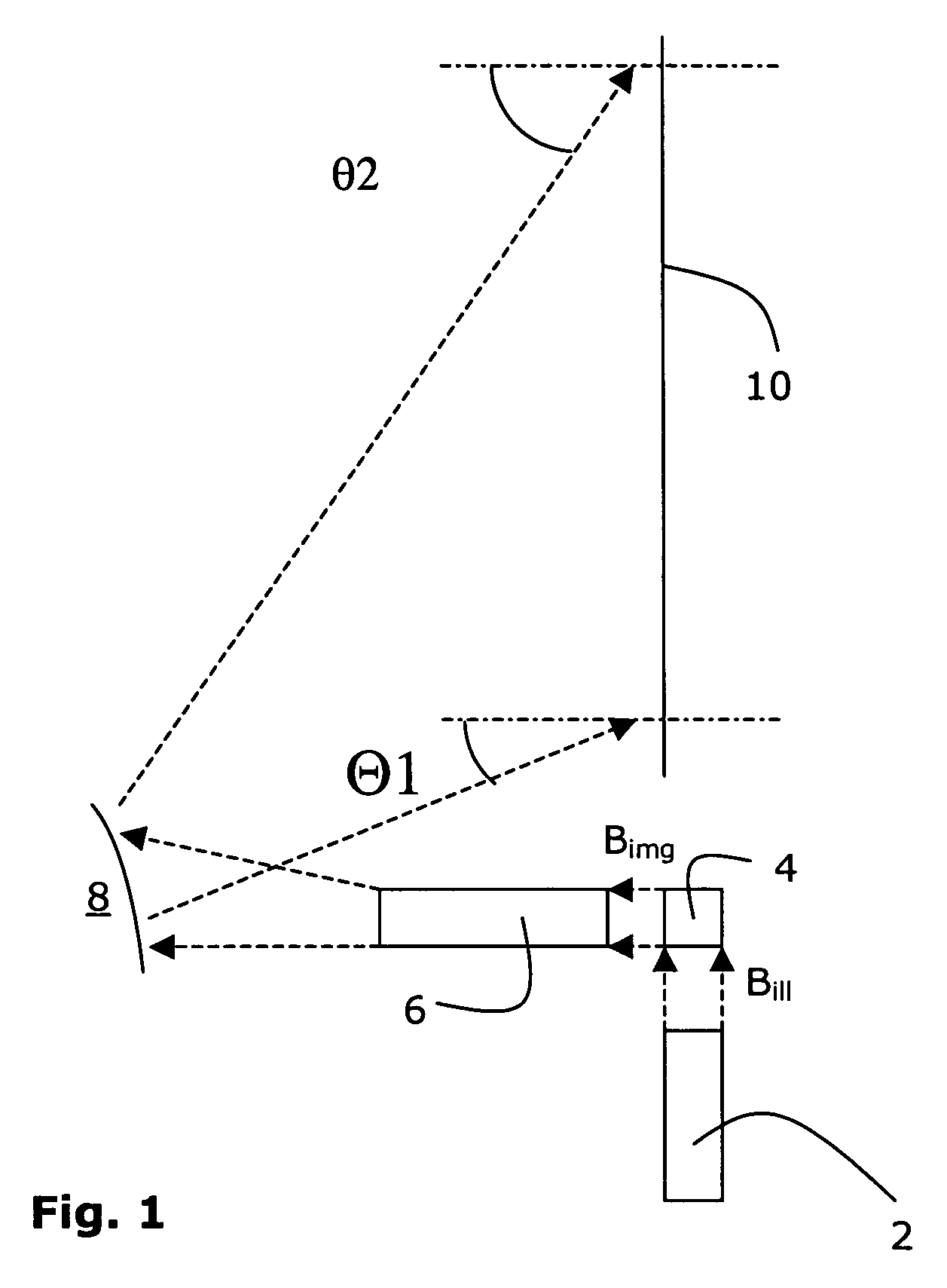
[0027]The display apparatus schematically represented on FIG. 1 has an illumination system 2 generating a primary bundle of light Bill received by an imager 4.

[0028]The imager 4 determines which parts of the bundle of light Bill are to be transmitted to an imaging system, thereby creating a secondary bundle of light Bimg representative of a picture to be displayed.

[0029]The imager 4 is for instance arranged as a matrix of pixels. Each pixel has an effect on the incoming ray of light (part of the primary bundle Bill) depending on how the corresponding pixel in the picture to be displayed should be lit.

[0030]The secondary bundle of light Bimg goes through a set of lenses 6 and is reflected by a reflector 8 onto the back of a viewing screen 10 in such a way that the set of lenses 6 and the reflector 8 define an imaging system, which projects the imager 4 on the viewing screen 10.

[0031]The viewing screen 10 carries transmissive elements (not represented), which generally collimate the i...


PUM


Abstract

The invention concerns a display apparatus with an imager illuminated by an illumination system and with an imaging system projecting an image on a viewing screen, wherein the brightness of the image on the imager has a variation over a given direction, and wherein the illumination system has light controlling elements for controlling the light distribution over the given direction.

Description

FIELD OF THE INVENTION[0001]The invention relates to a projection display apparatus.BACKGROUND OF THE INVENTION[0002]In a typical projection display apparatus, the picture produced by an imager illuminated by an illumination system is projected on a viewing screen thanks to an imaging system.[0003]It is naturally desirable for the user that the apparatus has a depth perpendicular to the screen as small as possible (slim projector). However, as the illumination and imaging systems are preferably located at one side of the apparatus (generally the bottom side), the small depth necessarily implies that light is incoming onto the screen with an angle varying over a wide range.[0004]As the transmission factor of the screen depends on the incoming angle of light, as in any optical system, this results in an uncontrolled heterogeneous brightness level over the screen (generally the bottom part is brighter).SUMMARY OF THE INVENTION[0005]The invention aims at a solution allowing designers to...

Claims


Application Information

Patent Timeline
Patent Type & Authority Patents(United States)
IPC IPC(8): G03B21/22G03B21/14G03B21/28G02B27/09G02B6/00G03B21/00G03B21/20H04N5/74
CPCG02B27/09H04N5/74G02B27/0994G03B21/2053G03B21/28H04N9/3129H04N9/3197
Inventor DRAZIC, VALTERO'DONNELL, EUGENEBENOIT, PASCALSCHUBERT, ARNO
Owner THOMSON LICENSING SA
Why Eureka
Try Eureka