
Method and apparatus for generalized recursive least-squares process for battery state of charge and state of health
a generalized, least-squares process and battery technology, applied in the field of battery packs, can solve the problems of reducing the utility of the prior art system, reducing the accuracy and efficiency of reflecting a battery system,
- Summary
- Abstract
- Description
- Claims
- Application Information
AI Technical Summary
Problems solved by technology
Method used
Image

Examples
Embodiment Construction
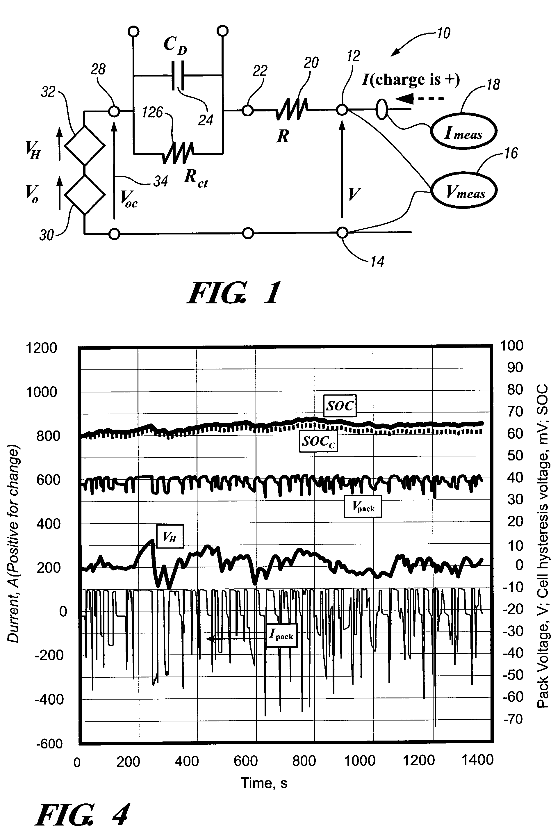
[0024]Referring now to the drawings in detail, in FIG. 1 numeral 10 generally indicates an equivalent circuit of a battery module suitable for the instant invention. Equivalent circuit 10 has a first end 12 and a second end 14, with a voltage V existing there between. A voltage measuring means 16 such as a voltmeter can be disposed between the first end 12 and second end 14 for a reading of the measured voltage V. An electric current measuring device 18 is adapted to measure an electric current at first end 12. A series resistance R 20 is disposed between a third point 22 and first end 12. A capacitance CD 24, and a parallel resistance Rct 26 are disposed between third point 22 and a fourth point 28. A battery voltage source Vo 30 and a hyteresis voltage source VH 32, coupled together in series, are disposed between a fourth point 28 and second end 14. Between fourth point 28 and second end 14, an open circuit voltage Voc 34 is defined.
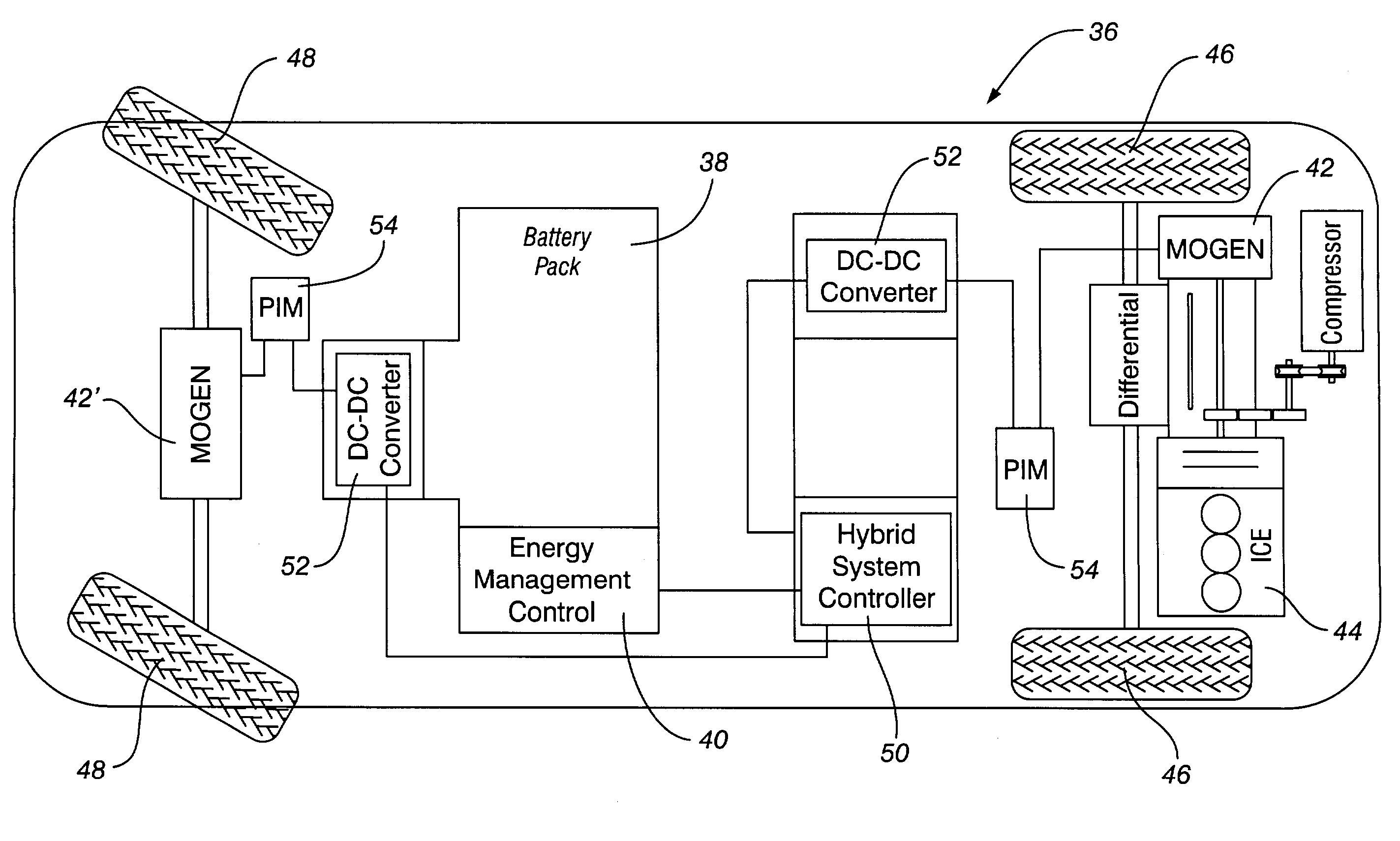
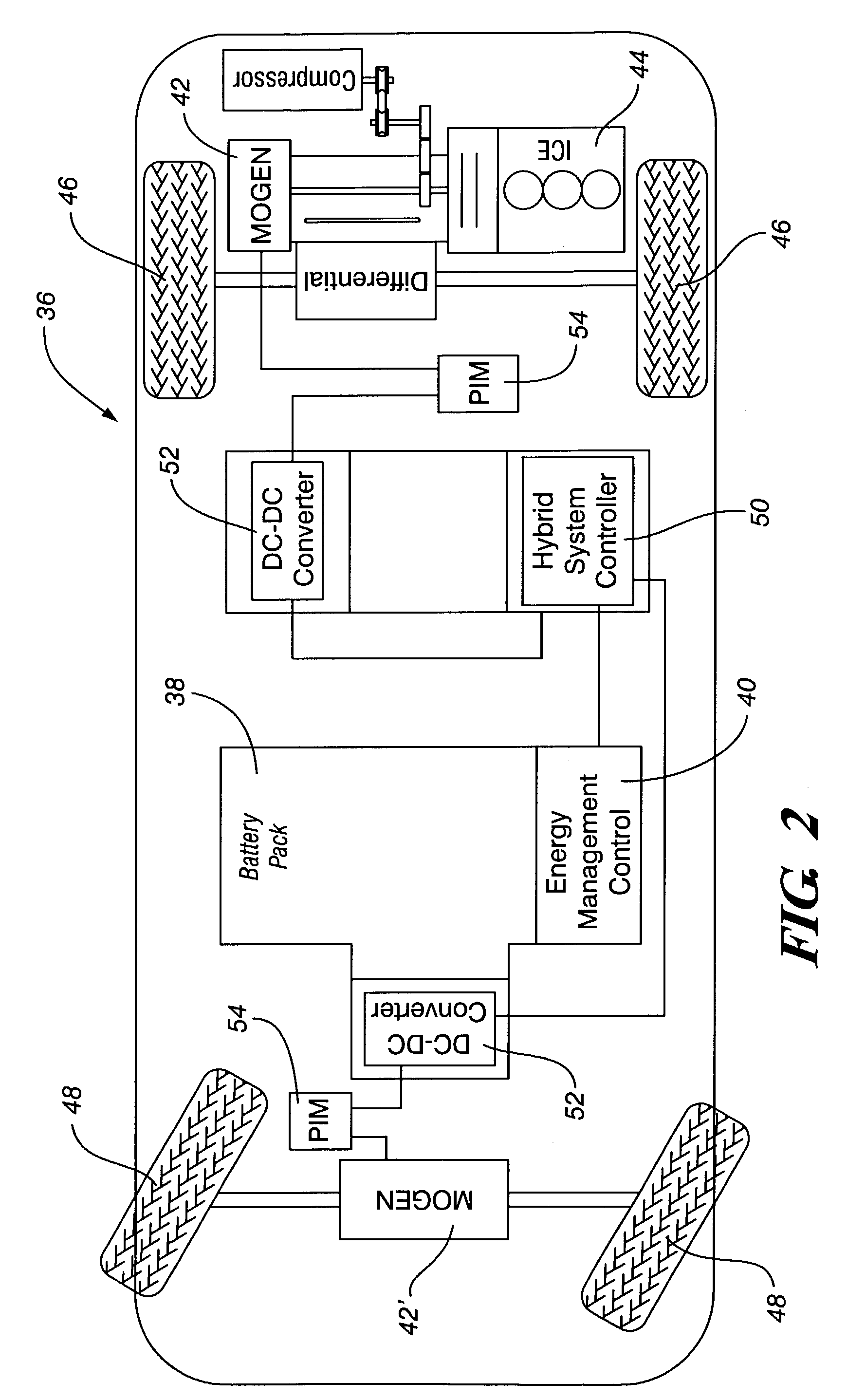
[0025]FIG. 2 is a diagrammatic view of a hybrid...
PUM
 Abstract
Description
Claims
Application Information