Objective lens driving device for optical head

a driving device and optical head technology, applied in the direction of heads, disposition/mounting, instruments, etc., can solve the problems of increasing the cost of components, complicated control of electric currents for tilting angle correction, and increasing the complexity of assembling work, so as to simplify the structure, and reduce the number of components

Inactive Publication Date: 2008-02-12
FUNAI ELECTRIC CO LTD
View PDF13 Cites 6 Cited by
  • Summary
  • Abstract
  • Description
  • Claims
  • Application Information

AI Technical Summary

Benefits of technology

[0013]An object of the invention is to provide an objective lens driving device for an optical head which drives the objective lens in three axial directions, namely, a focus direction, a track direction and a tilt angle direction, and has a simple structure with a decreased number of components, thereby permitting a low cost production to be realized and stabilized operation performance to be obtained.
[0015]By the above described means, it is possible to realize correction in the tilt angle direction by cooperative actions of the movable magnets provided on the lens holder and the tilt angle correcting coils provided on the base part, employing a simple and low-cost structure. Particularly, because the control current is supplied to the tilt angle correcting coils through the exclusive power supply lines, but not through the wires for supporting the lens holder, the structure will not be complicated with no need of increasing the wires in number, the production cost can be reduced, and the stabilized operation performance can be obtained.
[0017]Further, a plurality of the tracking coils may be provided on a front face side and a back face side of the lens holder respectively, and the focusing coil may be wound around an outer peripheral face of the lens holder in a direction perpendicular to the focus direction. In this manner, corrections in the focus direction and in the track direction can be performed with a simple structure.
[0018]Still further, one tracking coil and one focusing coil may be adjacently disposed on a front face side of the lens holder and another tracking coil and another focusing coil may be adjacently disposed on a back face side of the lens holder, and the tracking coil on one face of the lens holder may be provided so as to be opposed to the focusing coil on another face, and each of the fixed magnets may have on one face thereof a first portion in which the S pole and the N pole or the N pole and the S pole are arranged at both sides of a first boundary line extending in a direction perpendicular of the focus direction at a position opposed to the tracking coil, and a second portion in which the S pole and the N pole or the N pole and the S pole are arranged at both sides of a second boundary line extending in the focus direction at a position opposed to the focusing coil, and the adjacent same poles in the first portion and the second portion are formed of integral ferromagnetic material which has been magnetized so as to form a single magnetic area. With this structure, the focusing coil which is wound around the outer peripheral face of the lens holder in a direction perpendicular to the focus direction can be omitted, and the structure can be simplified. As the results, the number of components can be decreased, and the production cost can be reduced.
[0019]Still further, preferably in the fixed magnet, the first boundary line is formed so as to be opposed to a straight line passing through a center of the tracking coil, and the second boundary line is formed so as to be opposed to a straight line passing through a center of the focusing coil. In this manner, the tracking coils and the focusing coils can be driven and controlled with accuracy, and stabilized operation performance can be obtained.

Problems solved by technology

However, the above described structure has had a drawback that control of the electric currents for correcting the tilt angle has become complicated.
However, this structure has had such a problem that a driving force in the tilt angle direction maybe generated, and besides, a coil of a particular type having a flat structure may be required so as to be easily mounted, which leads to an increase of the cost for components.
There has been a further problem that because six wires are required for three axial driving, assembling work may become more complicated as compared with the structure employing the four wires.
Specifically, although the wires for supporting the lens holder must be assembled with a constant tension, it is difficult to make the tension constant in case of the six wires, because the wires may interfere one another.
Thus, a problem that stabilized operation performance can be hardly obtained, due to variations in the tension of the wires, may occur.

Method used


Image

  • Objective lens driving device for optical head
  • Objective lens driving device for optical head
  • Objective lens driving device for optical head

Examples


modified example

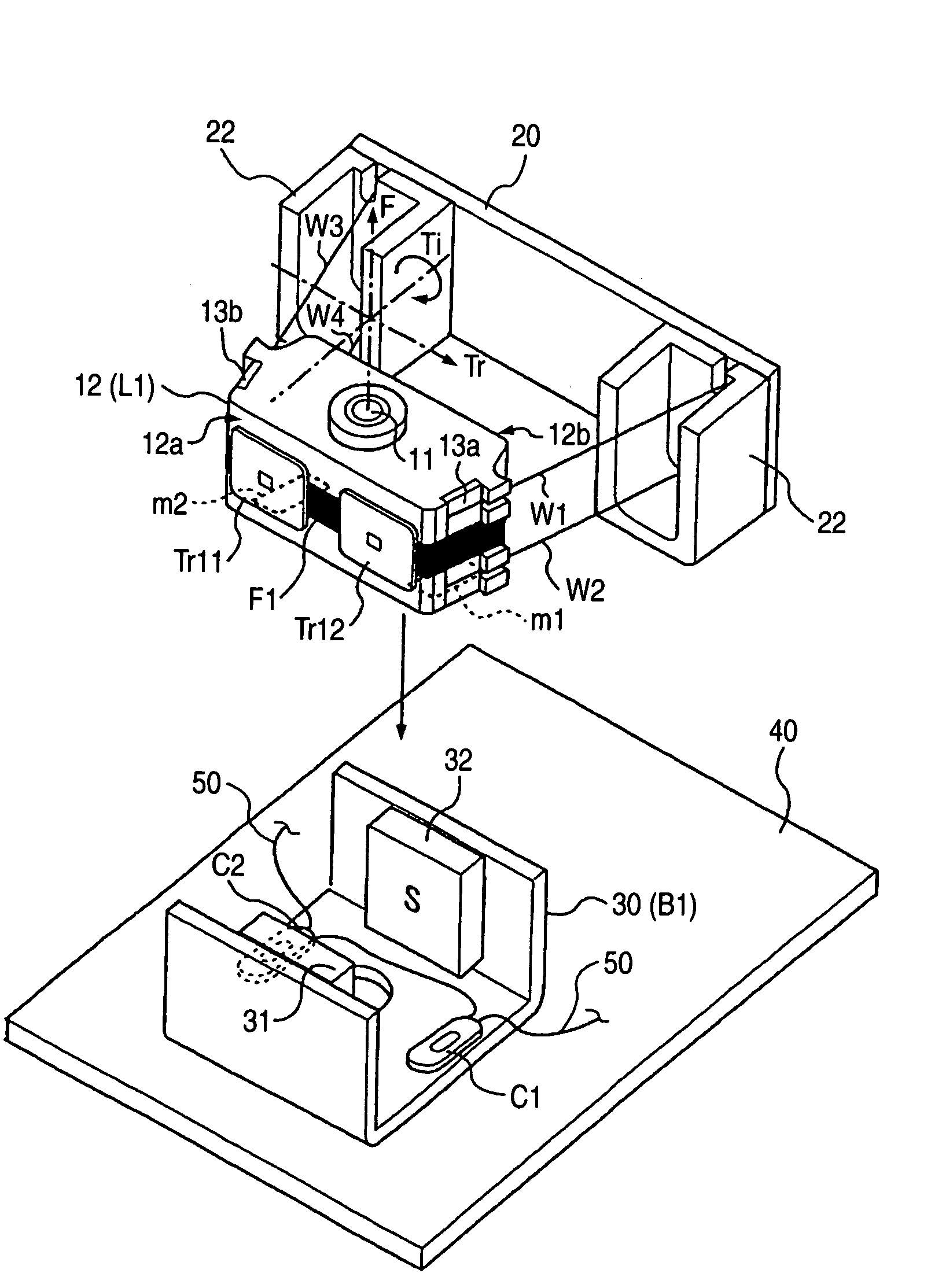
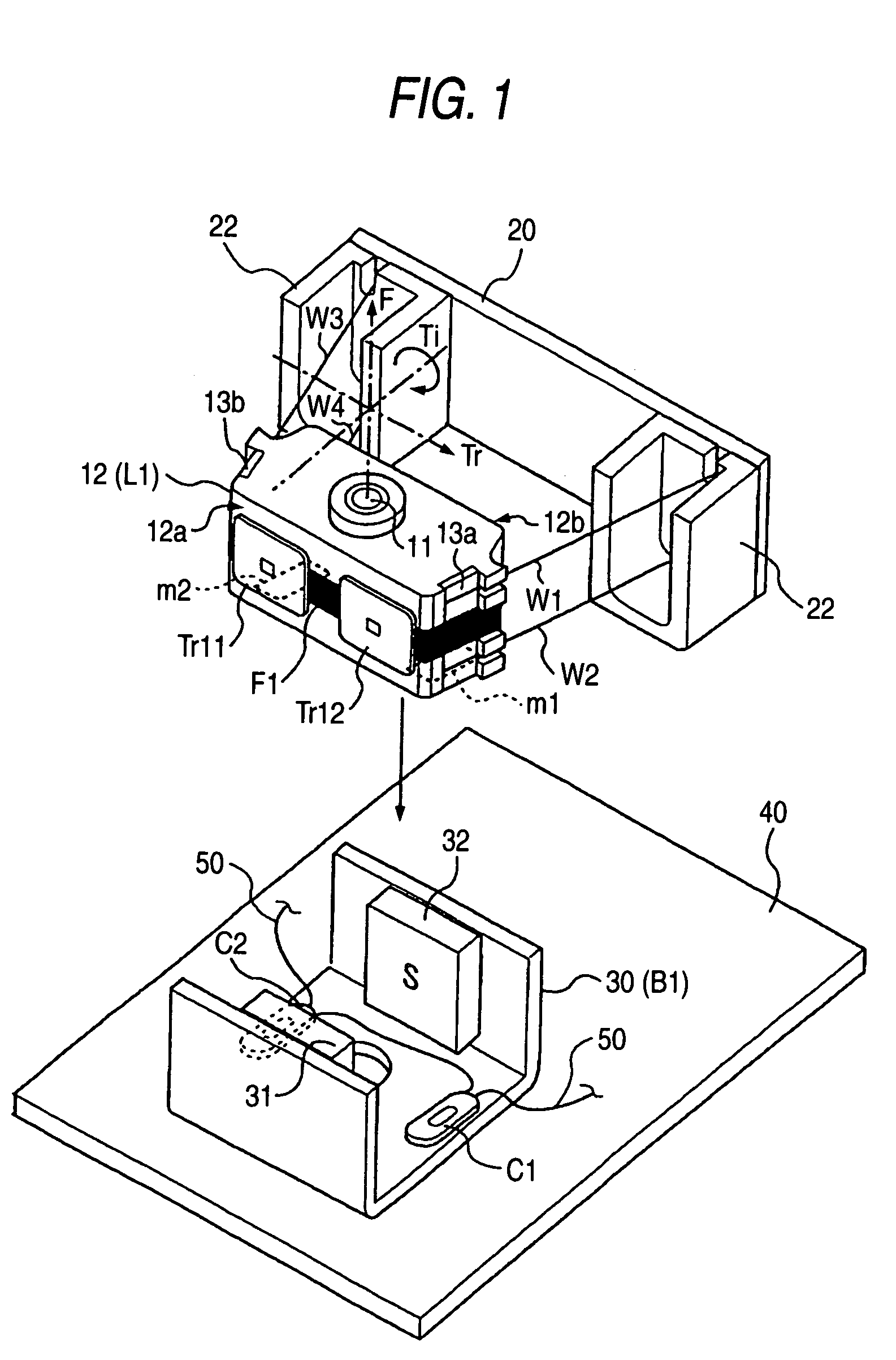
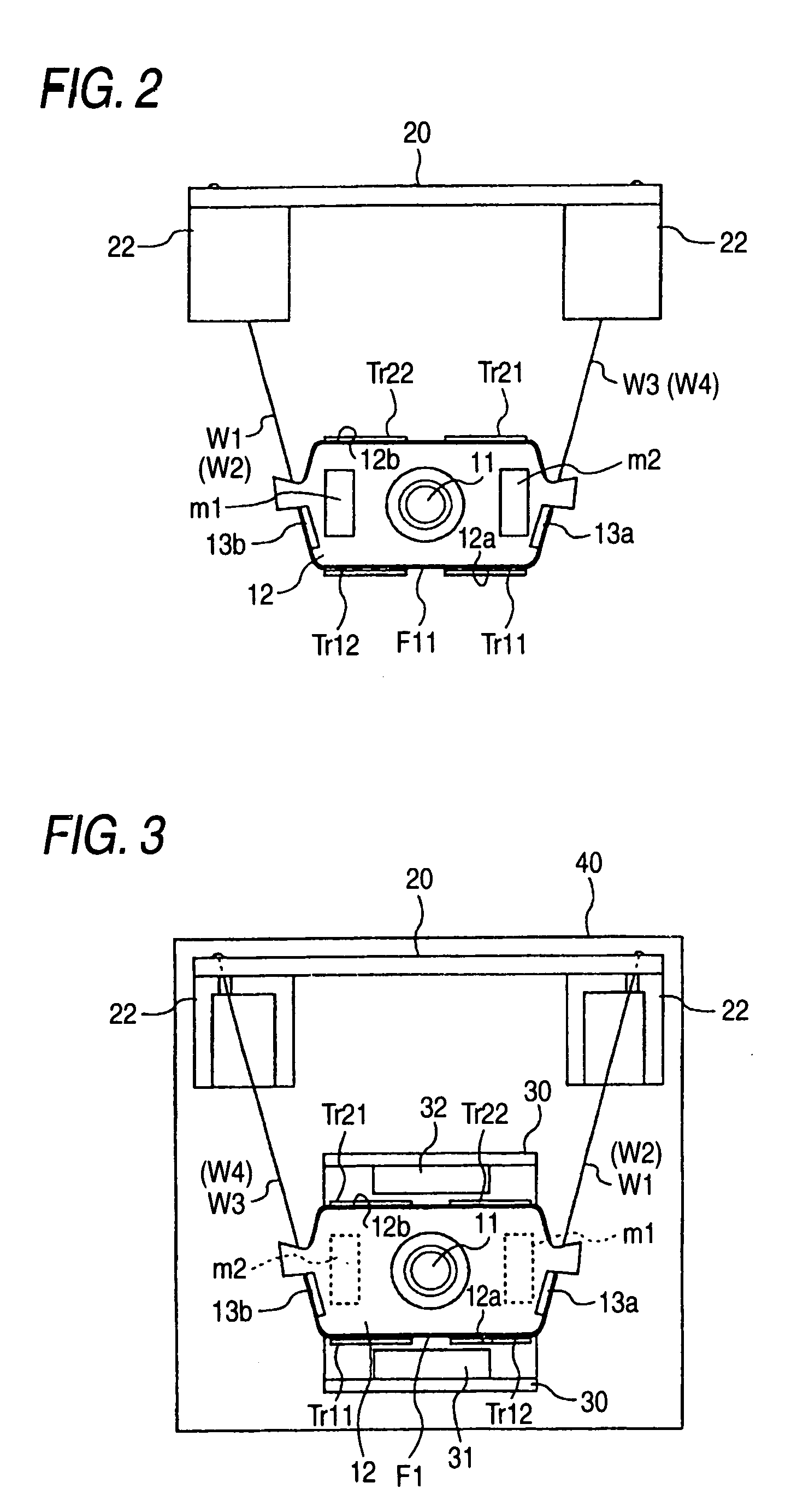
[0061]FIG. 8 shows another embodiment of the objective lens driving device according to the invention.

[0062]Although the yoke members for making the lines of induction extending from the magnets 31, 32 more straight are not provided in the first embodiment as shown in FIG. 1, it is also possible to construct the device in such a manner that the yoke members 30A, 30B are uprightly provided on the holder body 30, as shown in FIG. 8, while the lens holder 12 is formed with through holes 12A, 12B for the yoke members 30A, 30B to pass through. In this case, the holder body 30 is formed of magnetic material.

[0063]By providing the yoke members 30A, 30B in this manner, the lines of induction extending from the magnets 31, 32 can be made more straight as compared with the case where the yoke members 30A, 30B are not provided. As the results, drive and control of the objective lens by the control currents passed through the square type flat tracking coils Tr11, Tr12, Tr21, Tr22 and the focusi...


PUM

PropertyMeasurementUnit
sizeaaaaaaaaaa
currentaaaaaaaaaa
tilt angleaaaaaaaaaa

Abstract

An objective lens driving device for an optical head has a lens holder including one or more tracking coils, one or more focusing coils, a plurality of wires which supply control currents to the tracking coils and the focusing coils and which support the lens holder in a cantilever manner, and a pair of movable magnets which are provided on a lower face of the lens holder in a track direction with an interval therebetween. A base part includes a pair of fixed magnets which are arranged so as to be opposed to the tracking coils and the focusing coils of the lens holder thereby to act thereon, a pair of right and left coils for correcting tilt angles which are arranged so as to be respectively opposed to the movable magnets thereby to act thereon, and power supply lines for supplying control currents to the tilt angle correcting coils.

Description

BACKGROUND OF THE INVENTION[0001]1. Field of the Invention[0002]The present invention relates to an objective lens driving device for an optical head which is mounted on a disk driving apparatus for an optical disk, an optical magnetic disk, etc., and more particularly, to an objective lens driving device for an optical head employing a lens having high numerical aperture which requires adjustment of a tilt angle.[0003]2. Description of the Related Art[0004]In an optical disk driving apparatus, an art of correcting position of an objective lens of an optical head by displacing the lens respectively in a focus direction of light and in a radial direction (a track direction) of a disk which intersects with data rows on the disk has been heretofore known.[0005]As a conventional structure for conducting corrections in the focus direction and in the track direction, there has been known such a structure that providing coils and magnets respectively on side faces of a lens holder which ho...

Claims


Application Information

Patent Timeline
Patent Type & Authority Patents(United States)
IPC IPC(8): G11B7/00G02B7/08G02B7/04G03B5/04G11B7/09G11B7/095H02K33/12
CPCG11B7/0932G11B7/0933G11B7/0935G11B7/0956
Inventor MATSUI, TSUTOMU
Owner FUNAI ELECTRIC CO LTD
Why Eureka
Try Eureka