Combination vacuum manifold and support beam for a vacuum packaging system

a vacuum packaging and support beam technology, applied in the field of vacuum packaging arrangement, can solve the problems of relatively slow vacuum actuation and relatively complex mechanism of vacuum packaging machines of this type, and achieve the effects of reducing the amount of air, simplifying the movement of vacuum chambers, and simplifying the movemen

Active Publication Date: 2008-02-19
CP PACKAGING
View PDF34 Cites 12 Cited by
  • Summary
  • Abstract
  • Description
  • Claims
  • Application Information

AI Technical Summary

Benefits of technology

[0006]It is an object of the present invention to provide a vacuum packaging machine which simplifies movement of the vacuum chambers toward and away from the surfaces that support the packages to be evacuated. It is a further object of the invention to provide such a vacuum packaging machine which avoids the rotary, circular motion of prior art machines and simplifies the motion by which the vacuum chambers are moved into contact with the surfaces that support the packages to be evacuated. A still further object of the present invention is to provide such a vacuum packaging machine which significantly reduces the amount of air to be moved when the vacuum is to be supplied to the vacuum chambers, to accelerate the evacuation process and to shorten the vacuum cycle. A still further object of the present invention is to provide such a vacuum packaging machine which provides linear, reciprocating motion of the vacuum chambers together by means of a vacuum manifold to which the vacuum chambers are mounted.

Problems solved by technology

It can thus be appreciated that prior art vacuum packaging machines of this type involve a relatively complex mechanism for simultaneously rotating the plates and the vacuum chambers, and for raising and lowering the vacuum chambers at predetermined locations in the path of movement of the plates.
In addition, the long hose length between the vacuum source and the vacuum chambers results in relatively slow vacuum actuation, in that a significant amount of air must be moved from the vacuum chamber and the hose before vacuum is actually supplied to the interior of the vacuum chamber.

Method used


Image

  • Combination vacuum manifold and support beam for a vacuum packaging system
  • Combination vacuum manifold and support beam for a vacuum packaging system
  • Combination vacuum manifold and support beam for a vacuum packaging system

Examples


Embodiment Construction

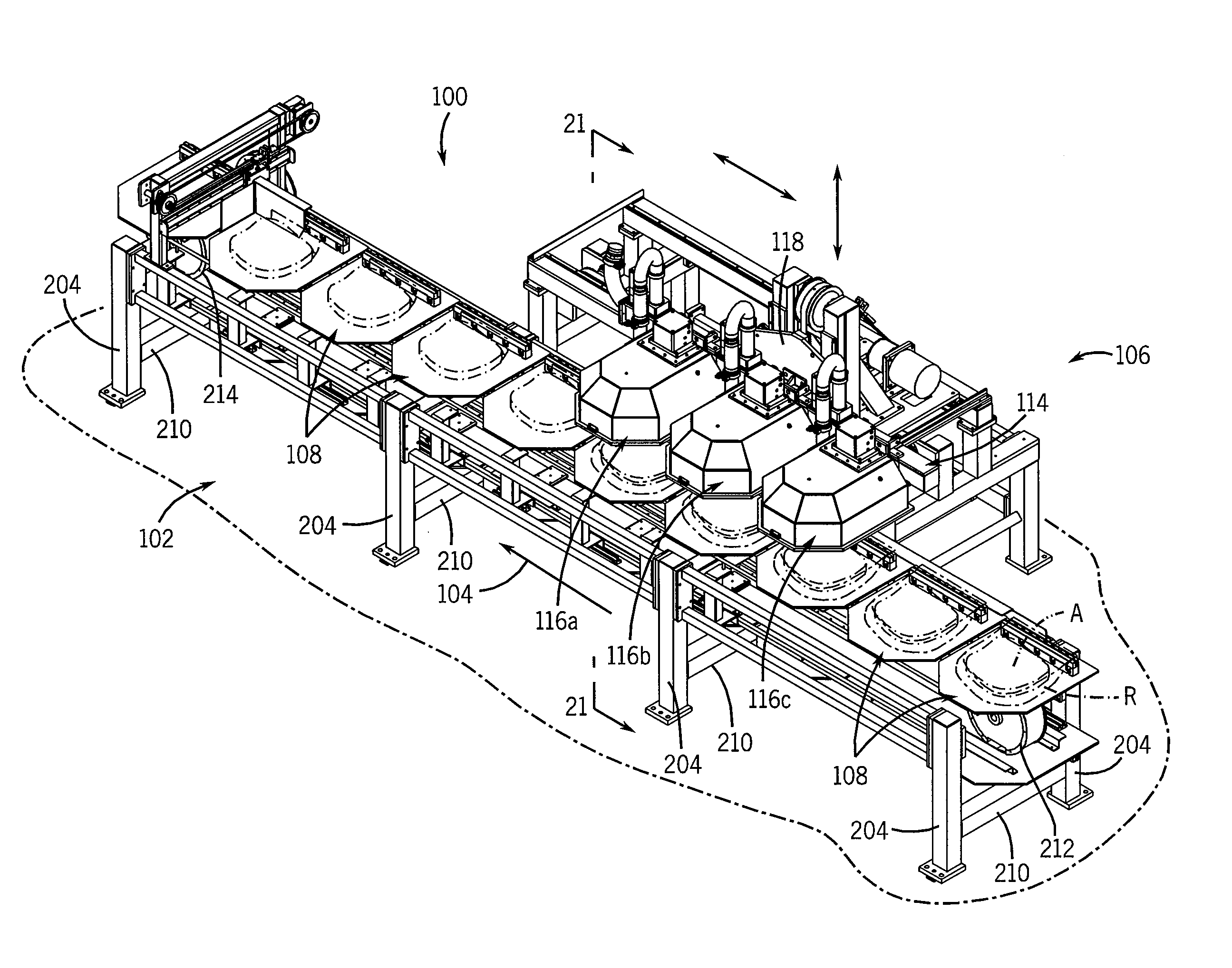
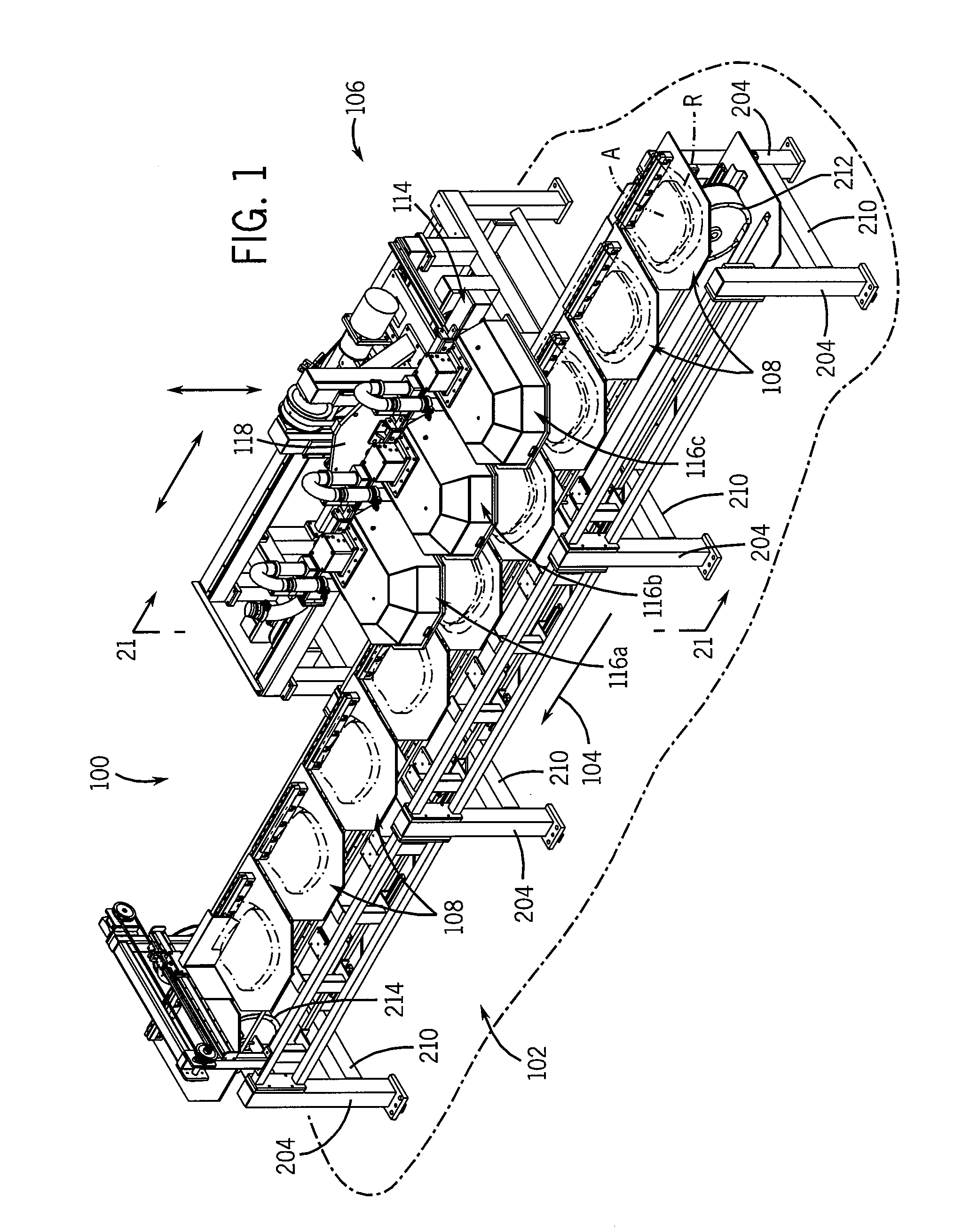
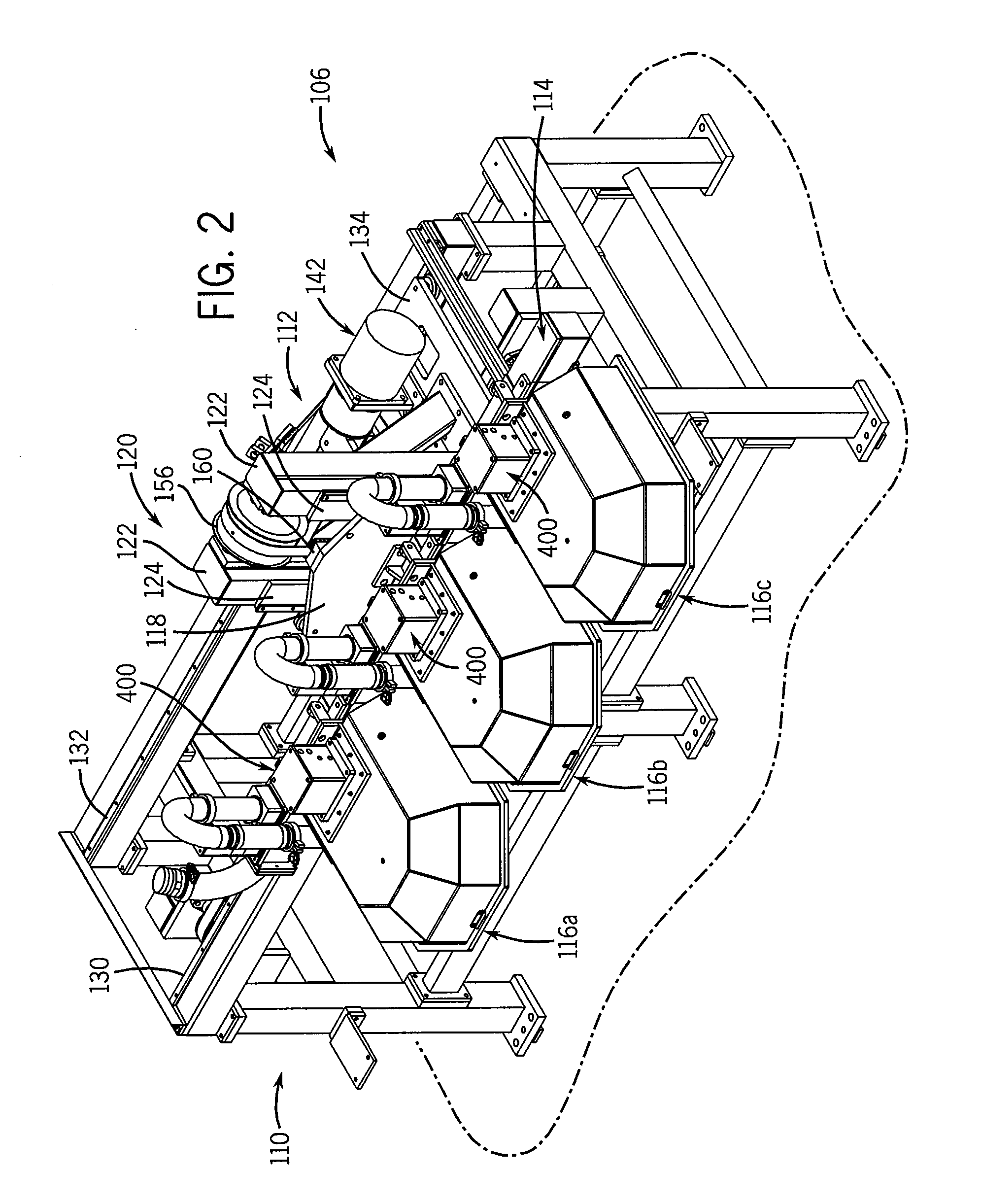
[0053]Referring to FIGS. 1 and 2, a linear motion reciprocating vacuum packaging system in accordance with the present invention is shown at 100. Generally, vacuum packaging system 100 includes a conveyor 102 that advances items to be packaged along the length of the vacuum packaging system 100 in a linear primary path of travel, denoted by arrow 104. Vacuum packaging system 100 further includes an evacuation arrangement shown generally at 106, which cooperates with conveyor 102 to evacuate and seal the items to be packaged as the items are conveyed by conveyor 102.

[0054]Conveyor 102 includes a series of platens 108, each of which is adapted to receive and support an article A contained within a receptacle R. Article A may be any article that is suitable for vacuum packaging, e.g. a perishable food product such as meat, cheese, etc. Receptacle R may be any satisfactory open-ended receptacle sized to receive article A and suitable for use in vacuum packaging, as is known in the prior...


PUM


Abstract

A vacuum packaging system includes a series of vacuum chambers that are carried by a movable combination support member and vacuum manifold, which defines an interior connected to a vacuum source. The vacuum chambers are in communication with the interior of the combination support member and vacuum manifold, through vacuum valves carried by the combination support member and vacuum manifold and conduits that extend between the vacuum valves and the vacuum chambers. The combination support member and vacuum manifold is movable between a lowered position and a raised position, to move the vacuum chambers into and out of engagement with platens that support packages located below the vacuum chambers. The vacuum chambers and platens are movable in an upstream to downstream direction, to advance the packages while the packages are being evacuated by the vacuum chambers.

Description

CROSS REFERENCE TO RELATED APPLICATIONS[0001]This application claims the benefit of provisional application Ser. No. 60 / 625,194 filed Nov. 5, 2004.BACKGROUND AND SUMMARY OF THE INVENTION[0002]This invention relates to vacuum packaging arrangement, and more particularly to a combination support member and vacuum manifold for use in a vacuum packaging arrangement.[0003]A typical vacuum packaging machine includes a series of components that move in a circular path about a central hub area. A series of radially spaced plates rotate about the central hub area, and each plate is adapted to support a package that is to be evacuated. A series of vacuum chambers or heads also rotate about the central hub area, and each vacuum chamber is located above one of the plates. The plates are movable between a loading area and a discharge area. During movement of the plates from the loading area to the discharge area, the vacuum chambers are sequentially lowered onto the plates to evacuate the packag...

Claims


Application Information

Patent Timeline
Patent Type & Authority Patents(United States)
IPC IPC(8): B65B31/04B65D81/20
CPCB65B31/022
Inventor BUCHKO, RAYMOND G.
Owner CP PACKAGING
Why Eureka
Try Eureka