Turn signal switch for vehicle

a turn signal switch and vehicle technology, applied in the direction of contact mechanisms, cycle equipments, optical signals, etc., can solve the problem of a relatively large entire length of the switch in the pushing-in/returning direction, and achieve the effect of increasing the sliding amount, increasing the rotation, and ensuring the insulation distance between the contacts

Active Publication Date: 2008-02-19
TOYO DENSO CO LTD
View PDF7 Cites 9 Cited by
  • Summary
  • Abstract
  • Description
  • Claims
  • Application Information

AI Technical Summary

Benefits of technology

[0007]Accordingly, it is an object of the present invention to provide a turn signal switch for a vehicle, wherein length of the switch can be reduced in the pushing-in / returning direction of a switch operating element.
[0009]With the first feature of the present invention, the pair of return springs provided between the return plate and the switch case exhibit the spring forces as follows: when the switch operating element is in the neutral position, the pin is urged to abut against the valley; when the switch operating element is swung to the left-turn or right-turn indicating position, the pin abutting against one of the return cam faces on the opposite sides of the valley is urged to return to the valley, i.e., the switch operating element is urged to return to the neutral position; and when the switch operating element is pushed to the pushed-in position, the first pin 47 is urged to return to the returned position. Further, the return plate and the pair of return springs are disposed in parallel on the switch operating element, thereby reducing the entire length of the switch in the pushing-in / returning direction of the switch operating element. Furthermore, the pair of return springs exhibit the spring forces from the opposite sides to return the switch operating element to the neutral position, thereby suppressing the wobbling of the switch operating element during operation thereof to improve the operational feeling.
[0011]With the second feature of the present invention, when at least both the left-turn and right-turn indicating circuits are in the open states, the region between the opposed surfaces of the movable contact holder and the stationary contact base is covered from above with the cover portion integrally provided on the movable contact holder. That is, the region between the opposed surfaces of the movable contact holder and the stationary contact base is covered from above when both the left-turn and right-turn indicating circuits are in the open states, i.e., in a state in which at least neither left-turn nor right-turn indicating operation is carried out, thereby preventing rainwater or the like from entering the region between the opposed surfaces of the movable contact holder and the stationary contact base from above.
[0013]With the third feature of the present invention, the resiliently urging means and the switch mechanism are disposed on the opposite sides of the switch operating element, thereby reducing the entire length of the turn signal switch in the pushing-in / returning direction of the switch operating element. Further, the position of the switch operating element can be changed depending on which side of the switch operating element the resiliently urging means and the switch mechanism are disposed on, thereby increasing the degree of freedom in arranging an operating portion of the switch operating element.
[0015]With the fourth feature of the present invention, the distance between the second pin operatively connected to the movable contact holder of the switch mechanism and the pivot is relatively increased to relatively increase the amount of sliding of the movable contact holder with the swinging of the switch operating element, thereby securing a sufficient insulation distance between the contacts of the switch mechanism. Further, a space required for movement of the resiliently urging means in the pushing-in / returning direction is reduced by the arrangement wherein the resiliently urging force of the resiliently urging means is applied to the first pin having a relatively large distance from the pivot, thereby downsizing the turn signal switch and increasing the degree of freedom in setting an operating load.

Problems solved by technology

However, in this conventional turn signal switch, the switch operating element and the return spring provided between the switch operating element and the switch case are connected to each other in series in the pushing-in / returning direction of the switch operating element, resulting in that the switch has a relatively large entire length in the pushing-in / returning direction.

Method used


Image

  • Turn signal switch for vehicle
  • Turn signal switch for vehicle
  • Turn signal switch for vehicle

Examples


Embodiment Construction

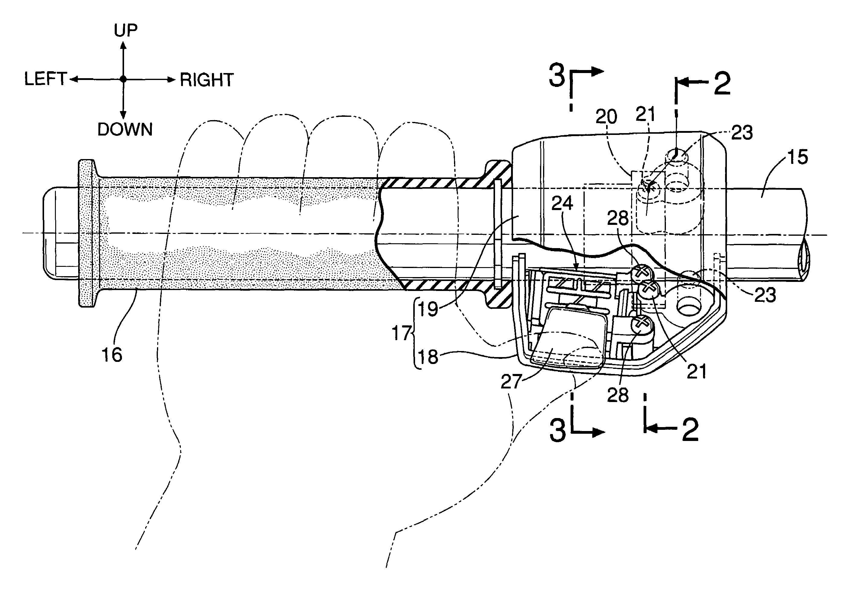
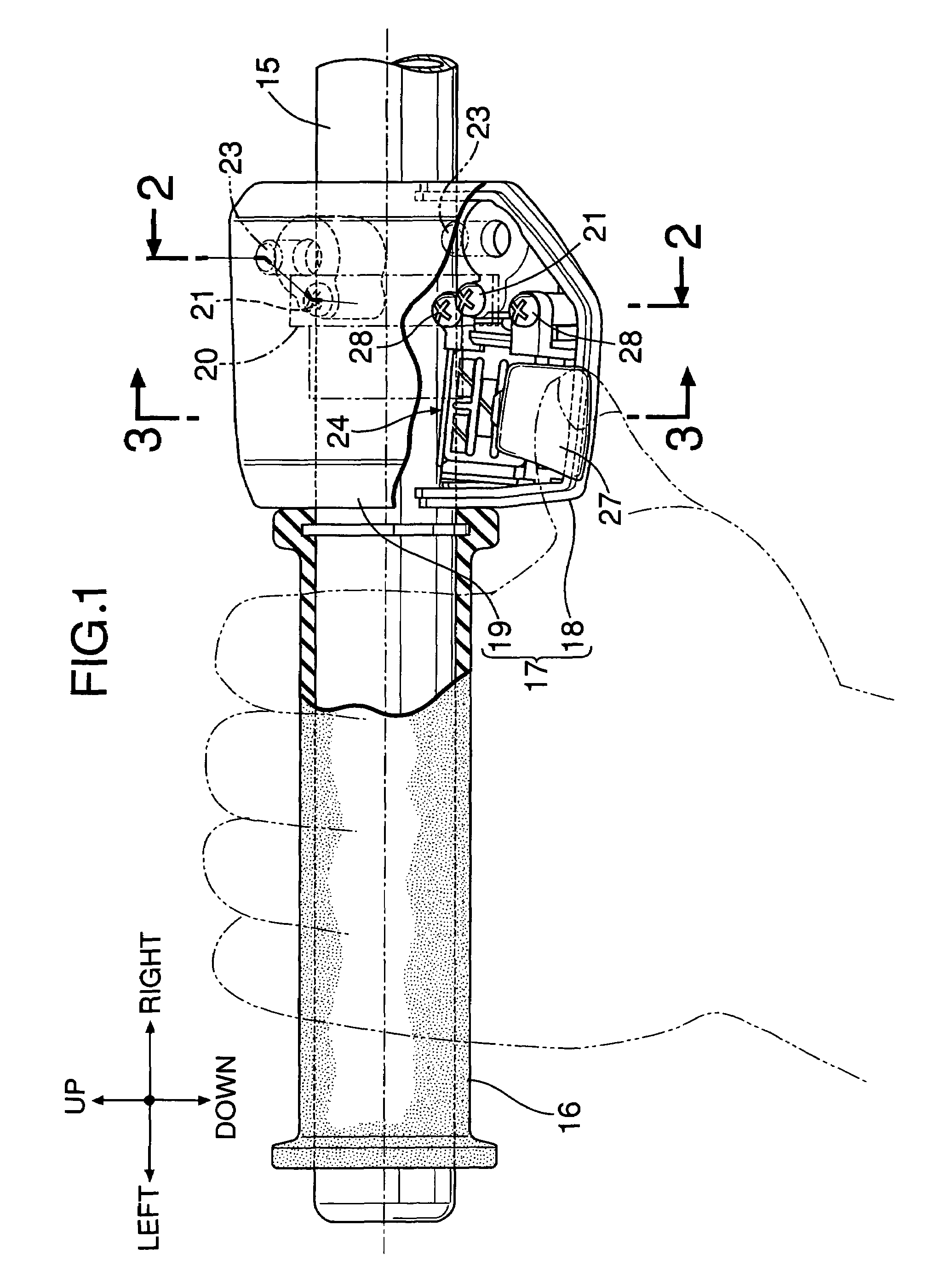
[0029]Referring first to FIG. 1, a grip 16 adapted to be grabbed by a rider's left hand is mounted at a left end of a steering handlebar 15, for example, for a motorcycle. A synthetic resin switch cover 17 is mounted to the steering handlebar 15 at a position inward of and adjacent to the grip 16.

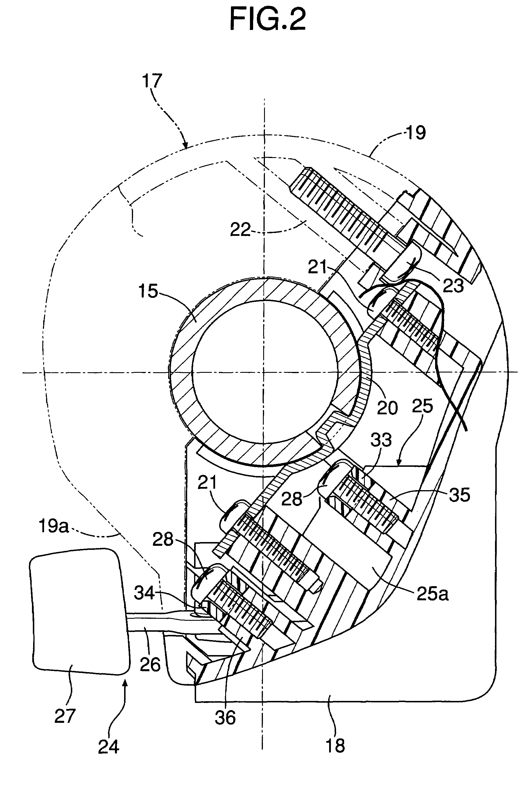
[0030]Referring also to FIGS. 2 and 3, the switch cover 17 comprises: a first cover half 18 which covers the steering handlebar 15 from obliquely below on a front side; and a second cover half 19 which covers the steering handlebar 15 from obliquely above on a rear side, the cover halves 18 and 19 being coupled to each other. The switch cover 17 is formed into a substantially cylindrical shape having end walls at its opposite ends, through which the steering handlebar 15 passes. A metal mounting member 20 is attached to the first cover half 18 by a plurality of, e.g., a pair of screw members 21, 21 so that the metal mounting member 20 abuts against and is positioned around an outer peripher...


PUM


Abstract

A turn signal switch for a vehicle includes: a resiliently urging means provided between a switch operating element and a switch case so as to urge the switch operating element toward a neutral position and a returned position. The resiliently urging means includes: a return plate having a guide recess which is provided at one end and against which abuts a first pin provided on the switch operating element, the return plate being slidably supported on the switch case; a pair of return springs exhibiting spring forces for urging the return plate in a direction to bring the pin into abutment against the guide recess. The guide recess is curved into a substantially triangular shape, and includes a valley and return cam faces on opposite sides of the valley. The return springs are provided on opposite sides of the valley and between the return plate and the switch case. Thus, it is possible to reduce the length of the turn signal switch in the direction of push-in / return of the switch operating element.

Description

RELATED APPLICATION DATA[0001]The present invention is based upon Japanese priority application No. 2006-155057, which is hereby incorporated in its entirety herein by reference.BACKGROUND OF THE INVENTION[0002]1. Field of the Invention[0003]The present invention relates to a turn signal switch for a vehicle, and particularly to a turn signal switch for a vehicle, comprising: a switch case; a pivot provided in the switch case; a switch operating element whose portion protrudes into the switch case, and which is supported by the pivot so that the switch operating element can be pushed-in and returned between a pushed-in position and a returned position which are spaced apart from each other in a direction perpendicular to an axis of the pivot, and so that, in the returned position, the switch operating element can be swung about the axis of the pivot among a neutral position, and a left-turn indicating position and a right-turn indicating position on opposite sides of the neutral pos...

Claims


Application Information

Patent Timeline
Patent Type & Authority Patents(United States)
IPC IPC(8): H01H3/16
CPCB60Q1/40B62J6/005B62J6/16B62K11/14B62K23/02B62J6/05B62J6/056B60Q1/34
Inventor TOZUKA, TSUTOMUNAKAMURA, TAKASHI
Owner TOYO DENSO CO LTD
Why Eureka
Try Eureka