Fish stringer system

a stringer and fish technology, applied in the field of fish stringing system, can solve the problems of inability to quickly connect/disconnect the cord line from the securing point and in-line securement or sheathing of the rod, injury to the operator of the fish stringer, cumbersome baskets and nets for wade fishers and operators of boats, etc., to achieve the effect of simple and fas

Active Publication Date: 2008-04-15
BRULL DWIGHT JOSEPH
View PDF14 Cites 4 Cited by
  • Summary
  • Abstract
  • Description
  • Claims
  • Application Information

AI Technical Summary

Benefits of technology

[0013]An object of the present invention to provide an improved fish stringing system comprising a shaft housing capable of releaseably holding and simultaneously sheathing a free end of a stringer rod attached to one end of a cord. The other end of the cord is connected to a floating stop. Another object of the present invention is to provide a simple and fast means to removeably secure the cord to a securing point, like a belt. In a preferred embodiment, the present invention is configured for use by wade or surf fishers. It another embodiment, the present invention could be secured to a boat or pole.

Problems solved by technology

Baskets and nets can be cumbersome for wade fishers and operators of boats.
A variety of different fish stringers have been developed over the years—but each are not capable of a quick connection / disconnection of the cord line from the securing point and in-line securement or sheathing of the rod when not in use.
The disclosed benefit of the Carpenter fish stringer does not secure the needle end of the cord to prevent fish uncoupling nor does it provide a sheath for the needle when not in use.
In fact, two ends of the needle are exposed when not in use and when in use—one end of the needle remains unsheathed which could result in injury to the operator of the fish stringer.
As disclosed, the needle is not securely fixed to the clip—it merely rests on the clip by means of gravity and there is no means to prevent upward movement of the unsheathed needle.

Method used


Image

  • Fish stringer system
  • Fish stringer system
  • Fish stringer system

Examples


Embodiment Construction

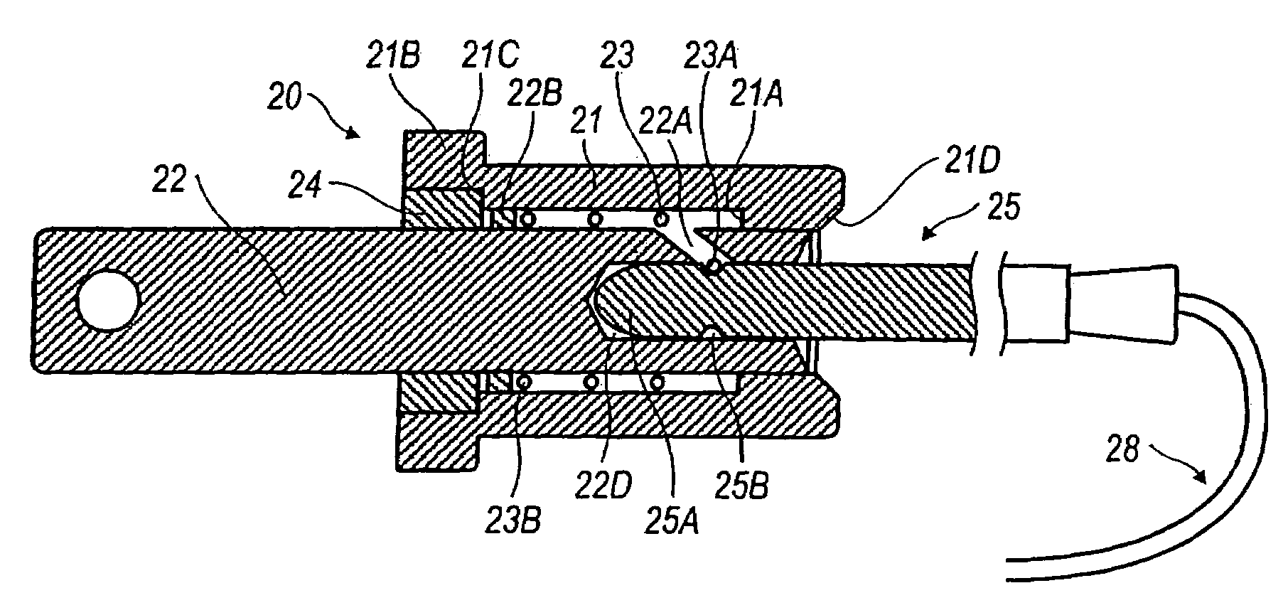
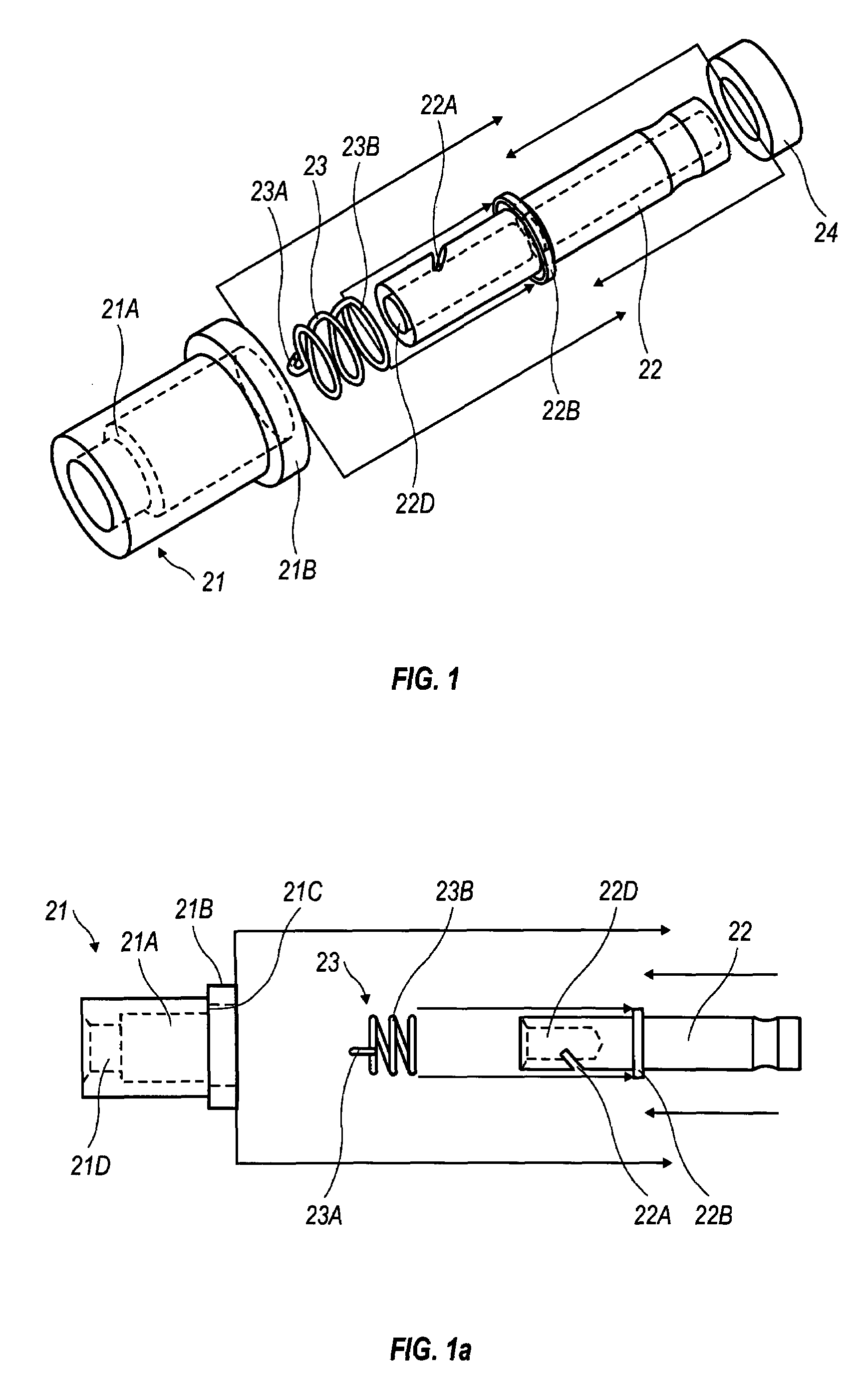
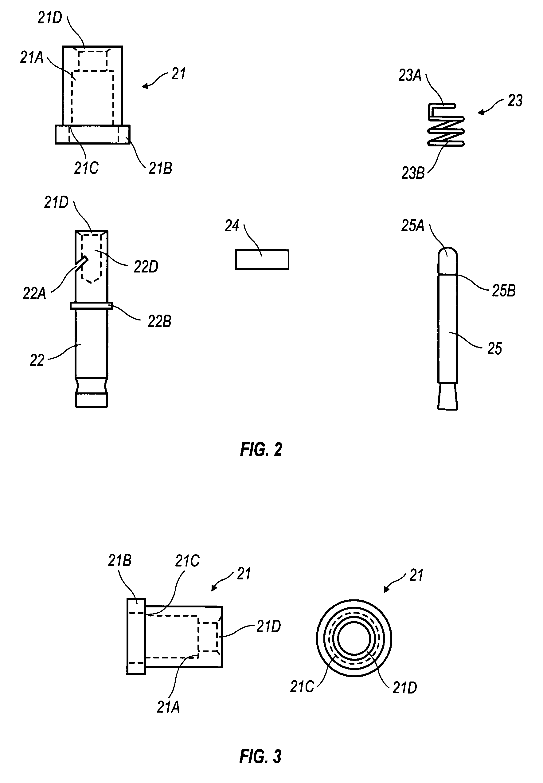
[0029]In its simplest form, the present invention is a fish stringing device which includes a spring loaded connector assembly designed to simultaneously releaseably couple and sheath a rod used to string fish upon a cord. The spring loaded connector assembly includes a rod receptacle inside a helical spring fixed within a tubular shaft housing. The helical spring is formed with a securing member projecting away and across a chord distance across one end of the helical spring. The securing member is slideably coupled to the rod receptacle by a slot diagonally formed in a wall of the rod receptacle. The rod has a groove formed about its circumference at a predetermined distance from a conical end of the rod. The groove releasably couples with the securing member to provide a quick connection by simply inserting and sheathing the conical end of the rod into rod receptacle. Quick disconnection and unsheathing of the rod requires pressing the spring loaded connector assembly to compress...


PUM


Abstract

A fish stringing device which includes a spring loaded connector designed to simultaneously releaseably couple and sheath a rod used to string fish upon a cord. The spring loaded connector includes a rod receptacle inside a helical spring fixed within a tubular shaft housing. The helical spring is formed with a securing member projecting away and across a chord distance at one end of the helical spring. The securing member is slideably coupled to the rod receptacle by a slot diagonally formed in a wall of the rod receptacle. The rod has a groove formed about its circumference at a predetermined distance from a conical end of the rod. The groove releasably couples with the securing member to provide a quick connection by simply inserting and sheathing the conical end of the rod into rod receptacle. Quick disconnection and unsheathing of the rod requires pressing the spring loaded connector to compress the spring which in turn causes the securing member to disengage from the groove and retract along the slot.

Description

BACKGROUND OF THE INVENTION[0001]1. Field of the Invention[0002]This invention relates to a fish stringing system, and more particularly, to a fish stringing system with a releaseable connector designed to simplify and hasten the attachment and removal of fish to a fish stringer.[0003]The applicable U.S. patent classification No. 403 / 321; 403 / 325; 224 / 103; 224 / 200; are in close relationship of said invention.[0004]2. Description of the Related Art[0005]Fishing, while viewed as an occupation, can be a recreational activity for many people around the world. Whether it be for relaxation, excitement or to earn income, fishing typically requires a means to secure and transport captured fish. Captured fish can be secured and stored in a basket, net or a fish stringer. The fish stringer is most commonly used to secure and transport the fish from the water to land or boat. Baskets and nets can be cumbersome for wade fishers and operators of boats.[0006]In its most simplest form, the typical...

Claims


Application Information

Patent Timeline
Patent Type & Authority Patents(United States)
IPC IPC(8): A01K65/00A01K1/00
CPCA01K65/00
Inventor BRULL, DWIGHT JOSEPH
Owner BRULL DWIGHT JOSEPH
Why Eureka
Try Eureka