Space-saving mounting fixture for use with an equipment rack

a technology for mounting fixtures and equipment, applied in the field of racks, can solve the problems of significantly longer power cables that are then required, and achieve the effect of convenient access

Inactive Publication Date: 2008-04-22
UNISYS CORP
View PDF71 Cites 19 Cited by
  • Summary
  • Abstract
  • Description
  • Claims
  • Application Information

AI Technical Summary

Benefits of technology

[0008]In accordance with the present invention, relatively small components can be received within regions of limited access using an installation fixture including a pair of mounting plates which are pivotally connected to each other by a hinge extending along corresponding edges of the respective mounting plates. One of the mounting plates includes a surface for fixed connection to a fra

Problems solved by technology

However, placement of the power strips along the upper and/or lower regions of the rack has the corresponding disadvantage that significantly longer power cables are then required to connect the power strips with the electrical co

Method used


Image

  • Space-saving mounting fixture for use with an equipment rack
  • Space-saving mounting fixture for use with an equipment rack
  • Space-saving mounting fixture for use with an equipment rack

Examples


Embodiment Construction

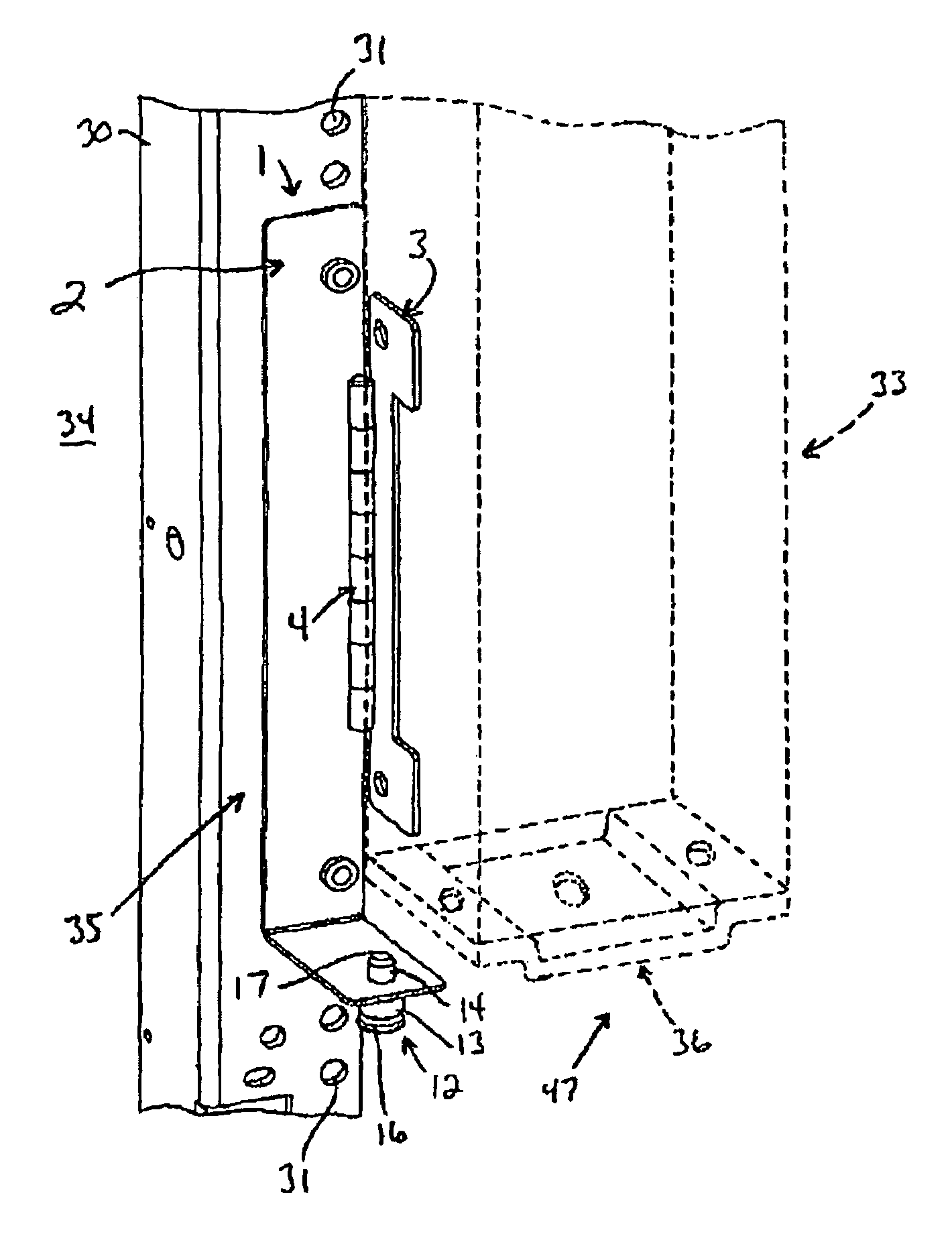
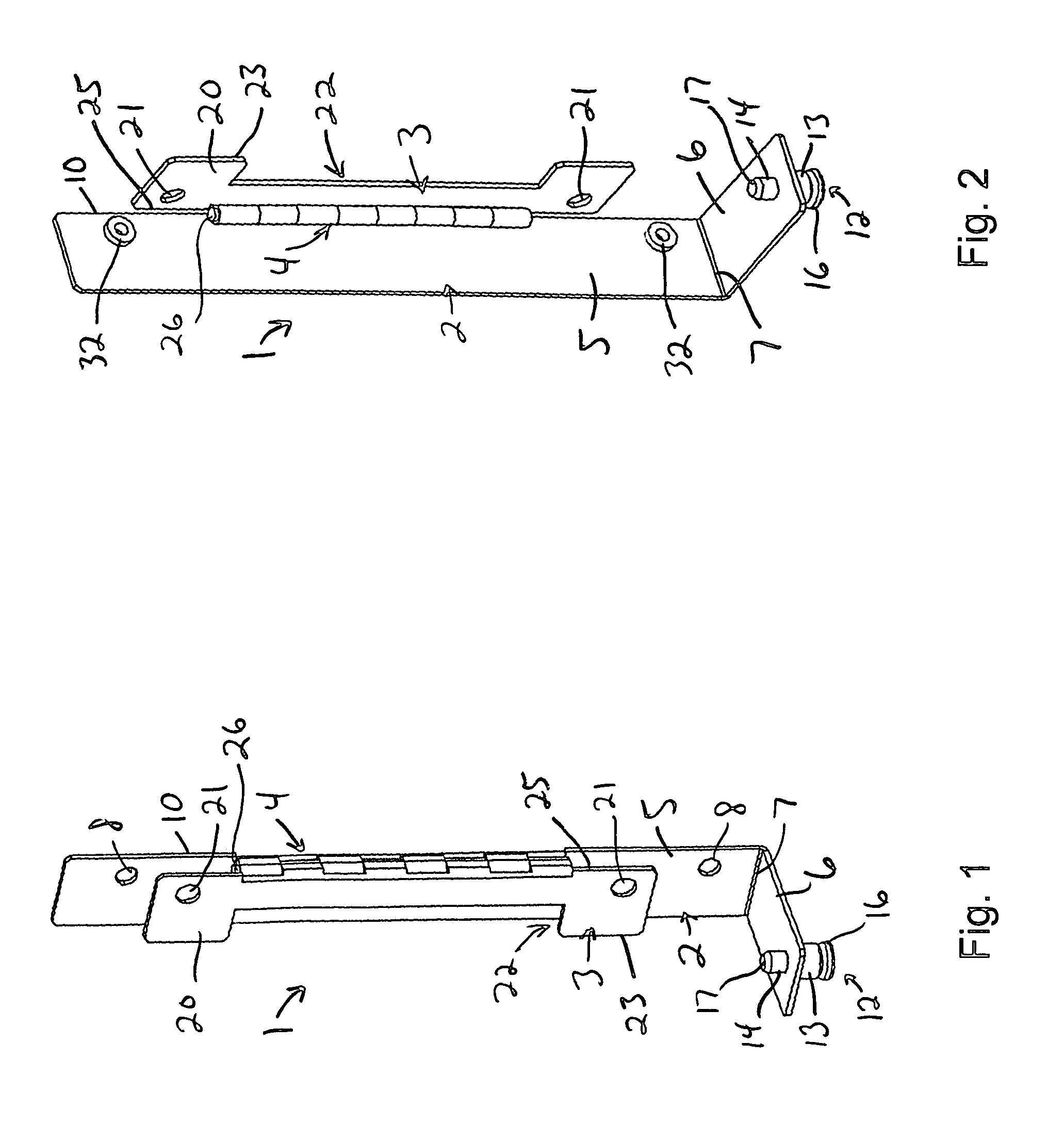
[0018]FIGS. 1 and 2 show a preferred embodiment of the installation fixture 1 of the present invention. In FIG. 1, the installation fixture 1 is shown in a closed, or retracted position. In FIG. 2, the installation fixture 1 is shown in an open, or deployed position. The installation fixture 1 is generally comprised of a pair of mounting plates 2, 3 which are connected by a hinge 4.

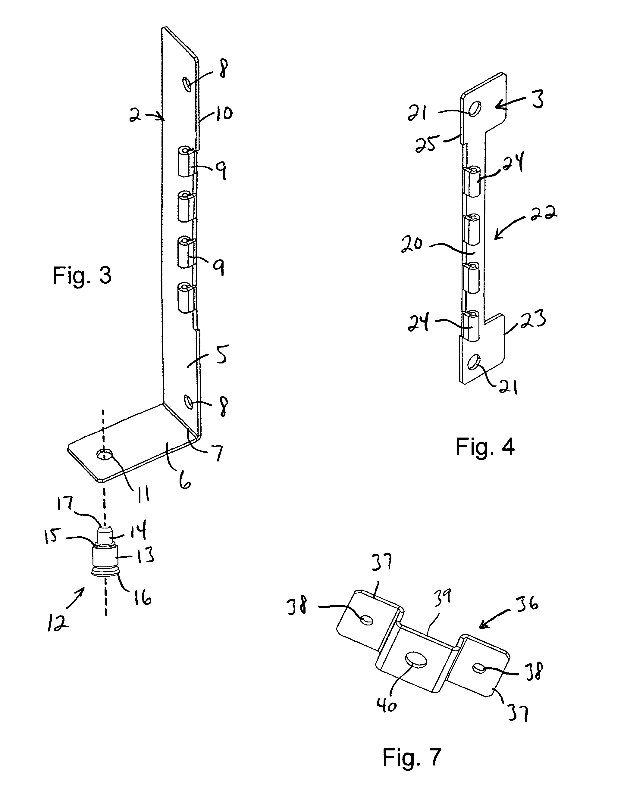
[0019]Referring also to FIG. 3, the mounting plate 2 includes a surface 5 having a flange 6 which extends from a transverse edge 7 of the surface 5. In the configuration illustrated, the surface 5 is planar, with an overall rectangular shape, and one or more apertures 8 are provided in the surface 5 of the mounting plate 2 for receiving conventional hardware for mounting the installation fixture 1 to a rack as will be described tore fully below. A series of barrels 9 for forming the hinge 4 are attached to and extend from a lateral edge 10 of the surface 5.

[0020]The flange 6 extends outwardly from the sur...


PUM


Abstract

Components can be received within regions of limited access present in an equipment-supporting rack using an installation fixture including a pair of mounting plates which are pivotally connected to each other by a hinge positioned along lateral edges of the respective mounting plates. One mounting plate includes a bracket for fixed connection to the rack, and the other mounting plate includes a surface for receiving a desired component. Rotation of the mounting plate receiving the component relative to the mounting plate fixed to the rack permits the component to be conveniently accessed when servicing is desired, and returned to the region of limited access during normal system operations. A locking mechanism is preferably provided for securing the component and the mounting plate which receives the component in desired position during normal system operations.

Description

BACKGROUND OF THE INVENTION[0001]This invention generally relates to racks and other types of chassis for receiving equipment, including but not limited to electronic equipment and the like, and more particularly, to a fixture for mounting such equipment in regions which are difficult to access.[0002]Support frames, generally referred to in the industry as “racks”, are conventionally used to receive desired electrical components such as circuit boards, modules or similar equipment and to support the received electrical components in desired position. Such racks can either be open, or enclosed to develop a housing (or cabinet) for receiving desired equipment.[0003]Racks of this general type are conventionally comprised of a series of framing elements which are combined to develop an enclosure for the equipment which is to be received in the resulting structure. To this end, a series of brackets is generally connected between a pair of support plates to develop an open enclosure for r...

Claims


Application Information

Patent Timeline
IPC IPC(8): F16C11/04A47F7/00
CPCH02B1/306H05K7/16Y10T16/540247Y10T16/52Y10T292/0867
Inventor YOON, SEUNGYUNLOUTH, TERRY W.
Owner UNISYS CORP
Why Eureka
Try Eureka