Vehicle headlamp and lamp unit

a headlamp and lamp unit technology, applied in the field of vehicles, can solve the problems of lack of novel design of the headlamp and the problem of the projection lens, and achieve the effect of reducing the depth dimension of the lamp room

Inactive Publication Date: 2008-05-06
KOITO MFG CO LTD
View PDF8 Cites 7 Cited by
  • Summary
  • Abstract
  • Description
  • Claims
  • Application Information

AI Technical Summary

Benefits of technology

[0010]In accordance with one or more embodiments of the present invention, a vehicle headlamp is capable of reducing the depth dimension of a lamp room as well as providing the light fixture design with a novelty.
[0023]As a result, it is possible to reduce the depth dimension of the lamp room accommodating the lamp unit. When the lamp unit is observed through the translucent cover, the projection lens tilted in two directions appears as arranged along the surface profile of the translucent cover, which gives a novelty to the lighting fixture design.
[0024]Moreover, it is possible to reduce the depth dimension of a lamp room and give a novelty to the lighting fixture design.
[0025]In accordance with one or more embodiments of the present invention, the convex curved surface constituting the front surface of the projection lens may be a spherical surface. In case the convex curved surface is an aspherical surface formed so as to position the rear focus point of the projection lens on the optical axis, aberration of the projection lens is removed. This allows accurate radiation control of light irradiated forward from the lamp unit.
[0026]A configuration is possible where the lamp unit is arranged in order for the upper end to be positioned near the optical axis in the vicinity of the rear focus point of the projection lens and the lamp unit is equipped with a shade for shielding part of the reflected light from a reflector. This configuration forms a light distribution pattern having a cutoff line at its upper end. In this practice, using the aspherical surface as the convex curved surface constituting the front surface of the projection lens can form a crisp cutoff line.

Problems solved by technology

However, the projection lens has problems described below since a plane constituting its rear surface is orthogonal to an optical axis.
Another problem is that, when the lamp unit is observed through the translucent cover, only its projection lens appears in the front direction of the vehicle, which lacks a novel design of the headlamp.

Method used


Image

  • Vehicle headlamp and lamp unit
  • Vehicle headlamp and lamp unit
  • Vehicle headlamp and lamp unit

Examples


Embodiment Construction

[0038]Embodiments of the invention will be described referring to drawings.

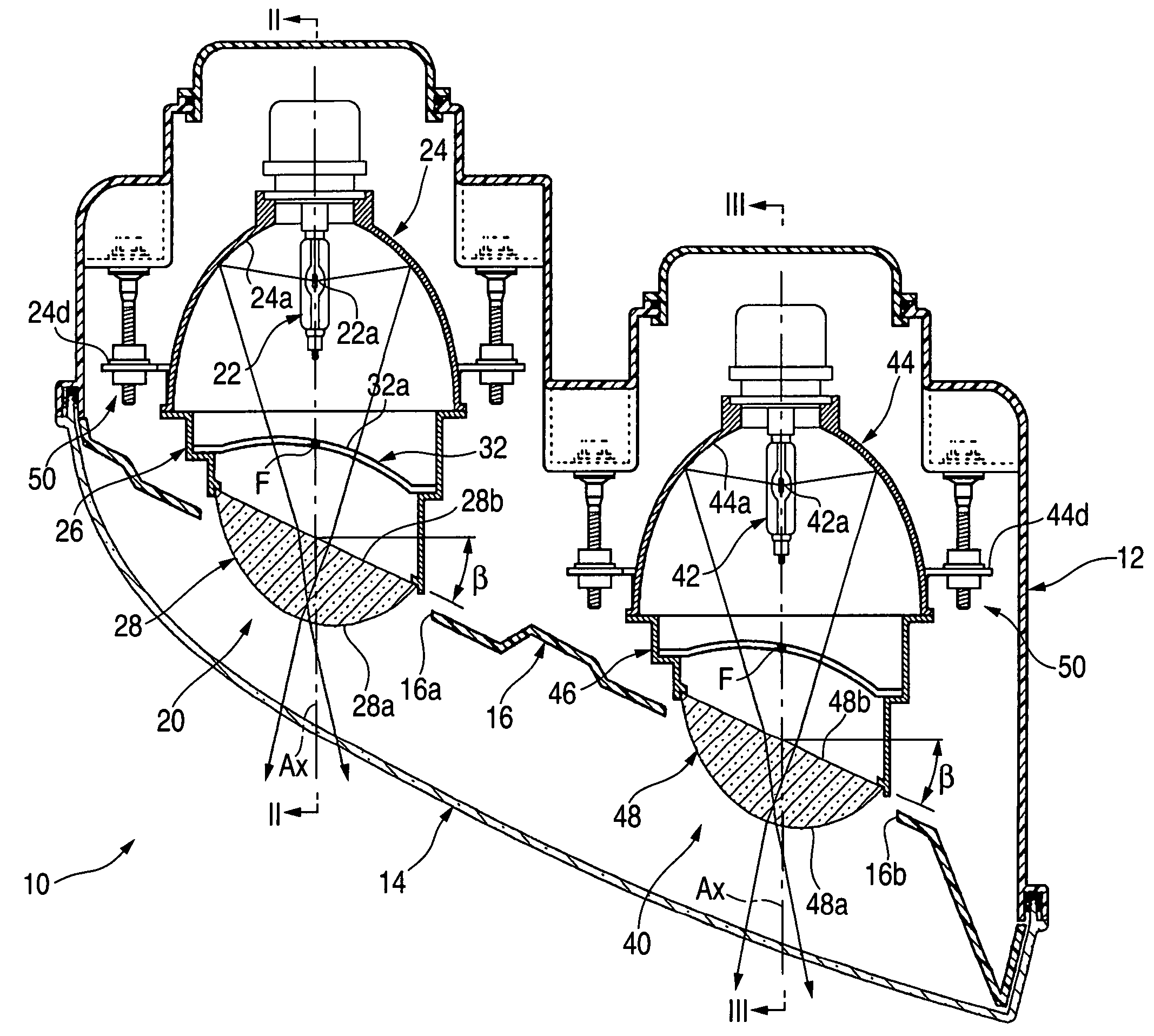
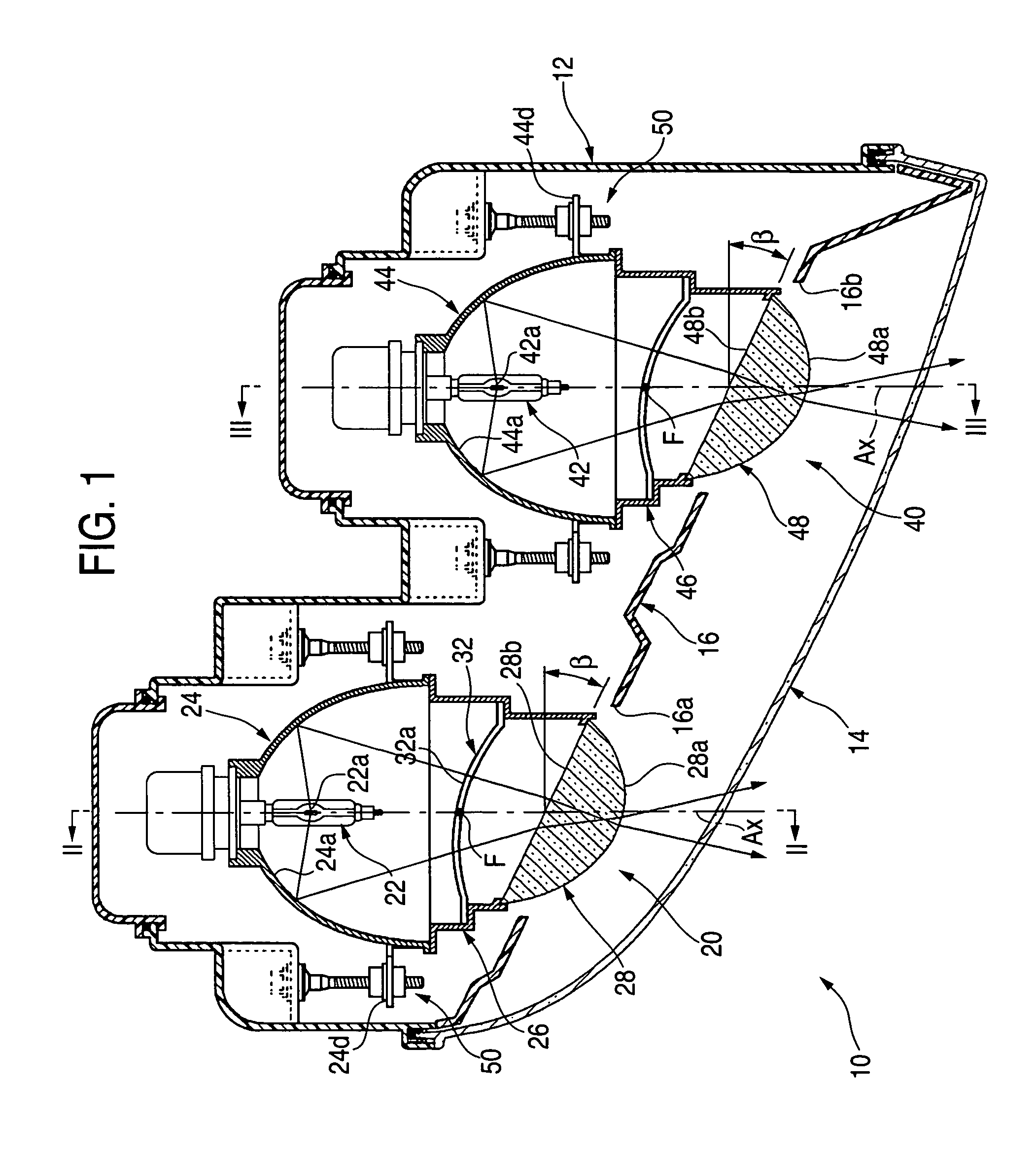
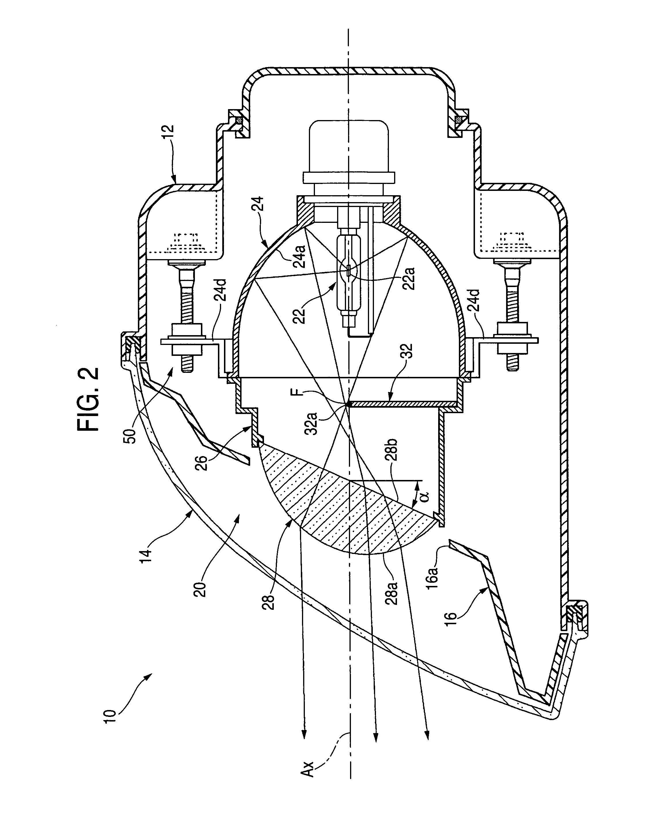
[0039]FIG. 1 is a horizontal cross section of a vehicle headlamp 10 according to an embodiment of the invention. FIGS. 2 and 3 are respectively a cross section of a II-II line and a cross section of a III-III line of the vehicle headlamp 10.

[0040]As shown in the figures, the vehicle headlamp 10 is a light fixture arranged at a front right section of a vehicle where two lamp units 20, 40 are adjacently accommodated in vehicle width direction in a lamp room formed by a lamp body 12 and a see-through translucent cover 14 attached to the front end opening of the lamp body. The vehicle headlamp 10 forms a low beam light distribution pattern by way of lighting of the lamp unit 20 as well as a high beam light distribution pattern by way of simultaneous lighting of the lamp units 20 and 40.

[0041]The two lamp units 20, 40 each has an optical axis Ax extending in the longitudinal direction of a vehicle and is supported...


PUM


Abstract

The projection lens of a lamp unit is configured as a plano-convex lens whose front surface is a convex curved surface and whose rear surface is a plane. The rear surface is constituted by a plane tilted upward with respect to a plane orthogonal to the optical axis and outward in a vehicle width direction.

Description

[0001]The present application claims foreign priority based on Japanese Patent Application No. P.2004-230660, filed on Aug. 6, 2004, the contents of which are incorporated herein by reference.BACKGROUND OF THE INVENTION[0002]1. Field of the Invention[0003]The present invention relates to a vehicle headlamp equipped with a so-called projector-type lamp unit.[0004]2. Related Art[0005]In general, a vehicle headlamp comprises a lamp room formed by a lamp body and a translucent cover attached to a front end opening of the lamp body, the lamp room accommodating a lamp unit having an optical axis extending in the longitudinal direction of a vehicle. Disclosed in JP-A-63-314701 is a projector-type lamp unit as one type of the lamp unit.[0006]In the projector-type lamp unit, a projection lens is disposed on an optical axis of the projector-type lamp unit, and a light source is disposed behind a rear focus point of the projection lens. Light from the light source onto a reflector is reflected...

Claims


Application Information

Patent Timeline
Patent Type & Authority Patents(United States)
IPC IPC(8): B60Q1/04F21V5/04F21Y101/00
CPCF21S48/1258F21S48/145F21S41/255F21S41/43
Inventor YAGI, TAKAYUKIUCHIDA, NAOKI
Owner KOITO MFG CO LTD
Why Eureka
Try Eureka