Enhanced performance torroidal coolant-collection manifold

a technology of torroidal coolant and manifold, which is applied in the direction of rocket engine plants, machines/engines, hot gas positive displacement engine plants, etc., can solve the problems of significant non-uniform flow in the coolant tube or passage, so as to reduce the pressure loss in the manifold

Active Publication Date: 2008-05-20
AEROJET ROCKETDYNE INC
View PDF7 Cites 5 Cited by
  • Summary
  • Abstract
  • Description
  • Claims
  • Application Information

AI Technical Summary

Benefits of technology

[0005]Accordingly, it is an object of the present invention to provide an improved manifold structure for use in cooling combustion chambers in an engine which reduces the pressure loss in the manifold.
[0006]It is a further object of the present invention to provide an improved manifold structure as above which improves the pressure uniformity in the coolant tubes or passages and the manifold.
[0008]In accordance with the present invention, a system for cooling a combustion chamber of an engine broadly comprises a plurality of coolant tubes or passages surrounding said combustion chamber, a torroidal coolant-collection manifold for receiving coolant from said coolant tubes or passages and for discharging said coolant through a discharge port, and means within the torroidal manifold for reducing pressure loss and improving pressure uniformity associated with said torroidal coolant-collection manifold. In a preferred embodiment of the present invention, the pressure reducing and pressure uniformity improving means comprises a plurality of turning vanes extending within said torroidal coolant-collection manifold.

Problems solved by technology

This abrupt and uncontrolled turn is the source of significant pressure loss in the manifold 18.
This pressure gradient contributes to non-uniform flow in the coolant tubes or passages.

Method used


Image

  • Enhanced performance torroidal coolant-collection manifold
  • Enhanced performance torroidal coolant-collection manifold
  • Enhanced performance torroidal coolant-collection manifold

Examples


Embodiment Construction

(s)

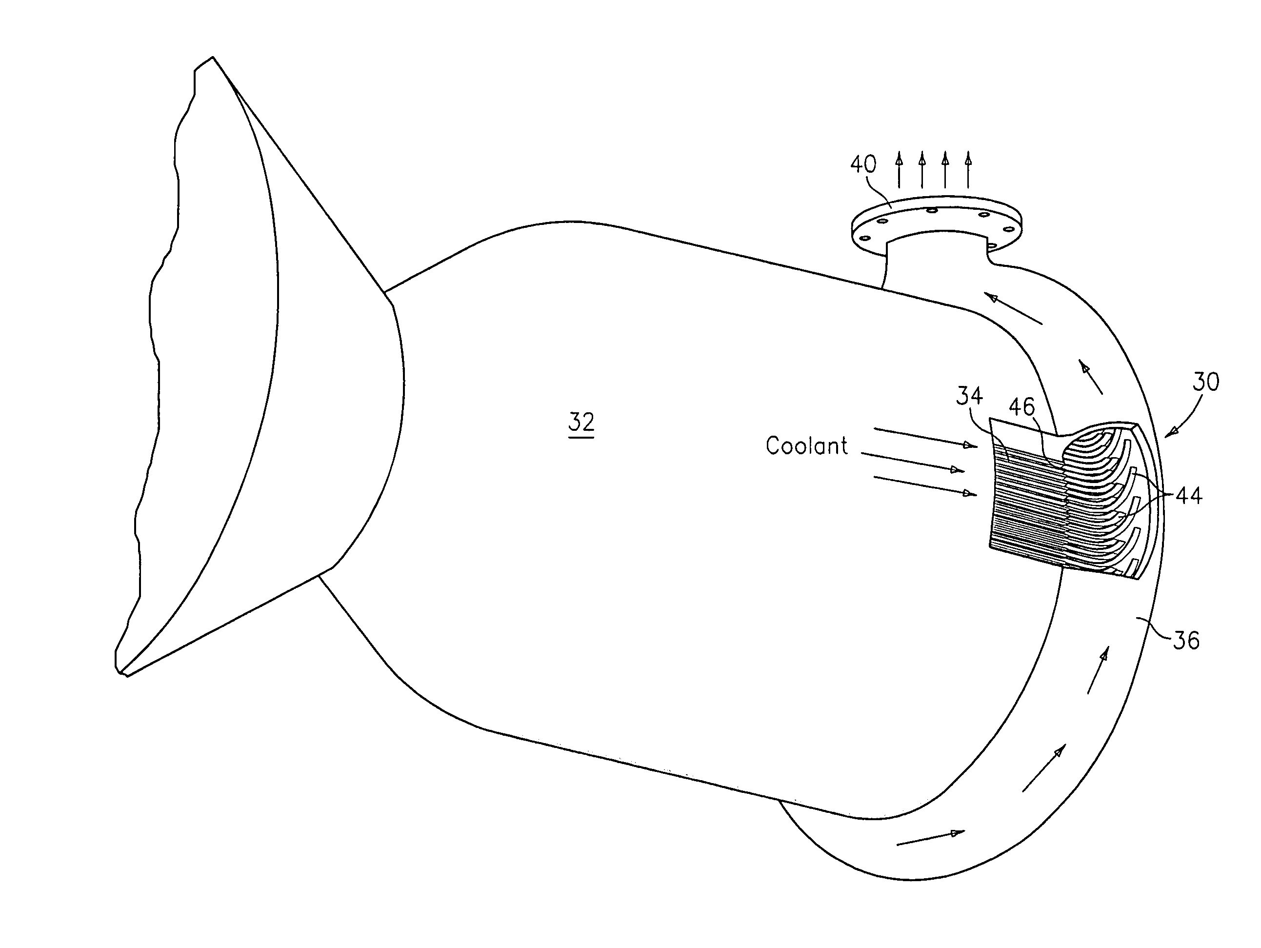
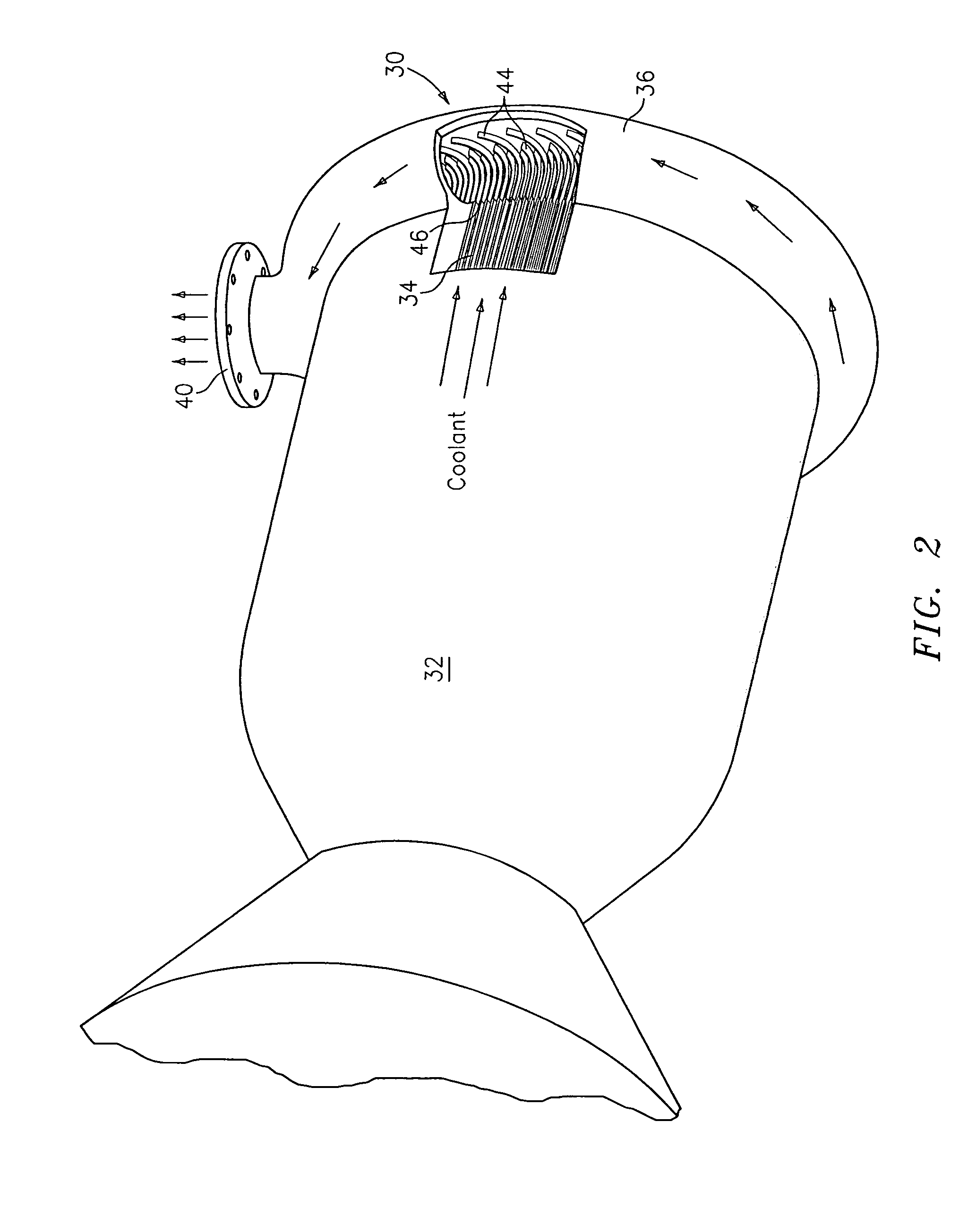
[0013]Referring now to FIGS. 2 and 3, an improved system 30 for cooling a combustion chamber 32 of an engine, such as a rocket engine, is provided. The system 32 has a plurality of tubes or passages 34 which form the cylindrical wall of the combustion chamber 32. The coolant tubes or passages 34 are used to transport a cooling fluid from a source (not shown) of the fluid to a torroidal coolant-collection manifold 36.

[0014]The torroidal coolant-collection manifold 36 is located adjacent an end 38 of each coolant tube or passage 34. The torroidal coolant-collection manifold 36 has a discharge port 40. While ordinarily the manifold 36 has a single discharge port 40, it may have a plurality of such ports if desired.

[0015]As can be seen from FIGS. 2 and 3, a plurality of vanes 44 are provided within the manifold 36. Each vane 44 is aligned with a respective coolant tube or passage 34 and is located adjacent an opening 46 in said respective coolant tube or passage 34. Each vane 44 is u...


PUM


Abstract

A system for cooling a combustion chamber of an engine, such as a rocket engine, is provided. The system has a plurality of coolant tubes or passages surrounding the combustion chamber, a torroidal coolant-collection manifold for receiving coolant from the coolant tubes or passages and for discharging the coolant through a discharge port, and a plurality of turning vanes within the torroidal manifold for reducing pressure loss and improving pressure uniformity associated with the torroidal coolant-collection manifold.

Description

BACKGROUND OF THE INVENTION[0001]The present invention relates to a system for cooling a combustion chamber of an engine, such as a rocket engine, and more particularly, to a torroidal coolant-collection manifold having enhanced performance for use in said engine.[0002]In a typical rocket engine, as shown in FIG. 1, coolant flows through a plurality of tubes or passages 10 that form the cylindrical wall 14 of a rocket combustion chamber 16. The coolant is discharged at relatively high velocity into a torroidal coolant-collection manifold 18, which typically has a single discharge port (not shown). Flow through individual tubes or passages 10 is influenced by pressures in the coolant-collection manifold 18. Since uniform flow through all of the tubes or passages 10 is desirable, pressures in the coolant-collection manifold 18 should be as uniform as possible.[0003]Typical rocket engine applications require that overall coolant pressure loss be minimized so that engine performance can...

Claims


Application Information

Patent Timeline
Patent Type & Authority Patents(United States)
IPC IPC(8): F02K11/00F02C1/04F02K99/00F02K9/64F02K9/97
CPCF02K9/64
Inventor CLARK, JIM A.RICCIARDO, MARK
Owner AEROJET ROCKETDYNE INC
Why Eureka
Try Eureka