Pump-free water-cooling system

a water-cooling system and pump-free technology, applied in the direction of lighting and heating apparatus, domestic cooling apparatus, semiconductor/solid-state device details, etc., can solve the problems of no degree of freedom in the installation posture, difficult to transport heat,

Inactive Publication Date: 2008-06-03
MITSUBISHI ELECTRIC CORP
View PDF19 Cites 33 Cited by
  • Summary
  • Abstract
  • Description
  • Claims
  • Application Information

AI Technical Summary

Benefits of technology

[0006]The present invention has been implemented in order to address the foregoing issues, and it is an object to provide a high-reliability, low-thermal-resistance pump-free water-cooling system that requires no external power supply, that allows heat to be transported in any direction, and that has large heat transportation capacity and lower thermal resistance.
[0008]In the pump-free water-cooling system according to the present invention, when the heat-exchange circulating solution receives in the third transporting route heat from the heating heat exchanger, the heat-exchange circulating solution raises its temperature; boiling occurs in the third transporting route, thereby producing vapor bubbles; and the heat-exchange circulating solution and the vapor bubbles travel through the circulating-solution transporting route by means of the buoyant force that acts on the vapor bubbles. Traveling of the vapor bubbles causes part of the heat received from the heating heat exchanger to be radiated through the heat radiator provided on the outer wall of the heat-exchange circulating solution container. In addition, traveling of the heat-exchange circulating solution causes the remaining portion of the heat received from the heating heat exchanger to be radiated through the sensible-heat-emitting heat exchanger. In conventional gravity-type heat pipes, the latent heat transportation by means of vapor bubbles to the heat radiating portion is performed merely as described herein; in contrast, in the present invention, the latent heat transportation by means of vapor bubbles to the heat radiator and the sensible heat transportation by means of circulating solution to the sensible-heat-emitting heat exchanger is performed, whereby a large amount of heat can be transported. Moreover, because the heat transportation to the sensible-heat-emitting heat exchanger is performed merely by means of liquid, it is not required to provide the sensible-heat-emitting heat exchanger above the heating heat exchanger; therefore, the sensible-heat-emitting heat exchanger can be provided at any position, whereby the degree of freedom in terms of a heat-radiation position increases.

Problems solved by technology

Because the capillary-type heat pipe that has the structure described above refluxes working fluid to a heating portion (a portion in which a heating element is disposed) by means of capillary force, i.e., extremely small driving force, its maximal heat transportation capacity is small, and it is difficult to reflux the working fluid in the direction reverse to gravity direction; therefore, the problem of difficulty in transporting heat has been posed.
In contrast, because a gravity-type heat pipe refluxes working fluid to a heating portion by utilizing gravity, there was imitation of posture, i.e., that the heat radiating portion must definitely be situated higher than the heating element; therefore, a problem has been posed wherein there was no degree of freedom in terms of installation posture.

Method used


Image

  • Pump-free water-cooling system
  • Pump-free water-cooling system
  • Pump-free water-cooling system

Examples


embodiment 1

[0029]Embodiment 1 of the present invention will be discussed below referring to the accompanying drawings.

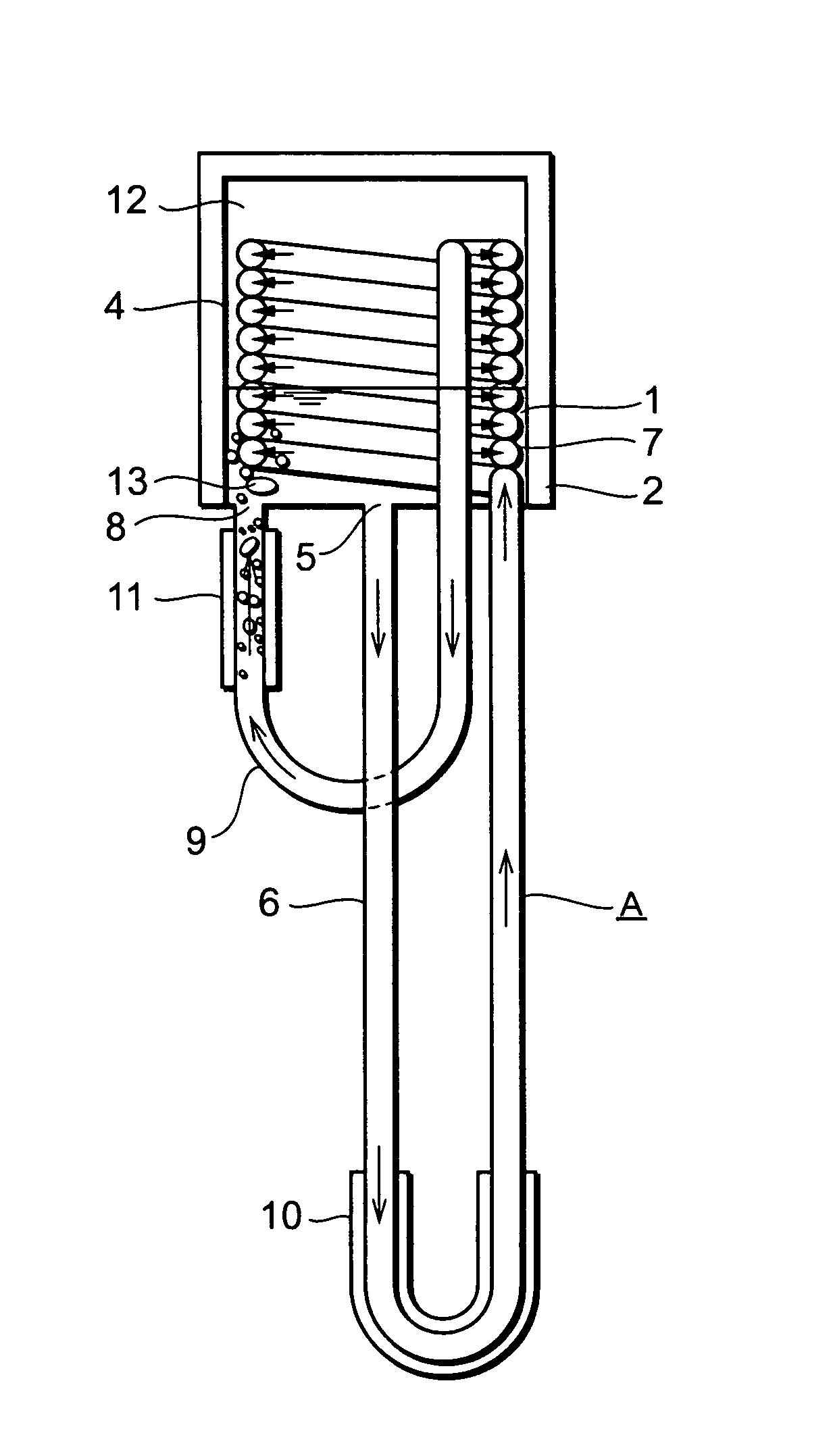
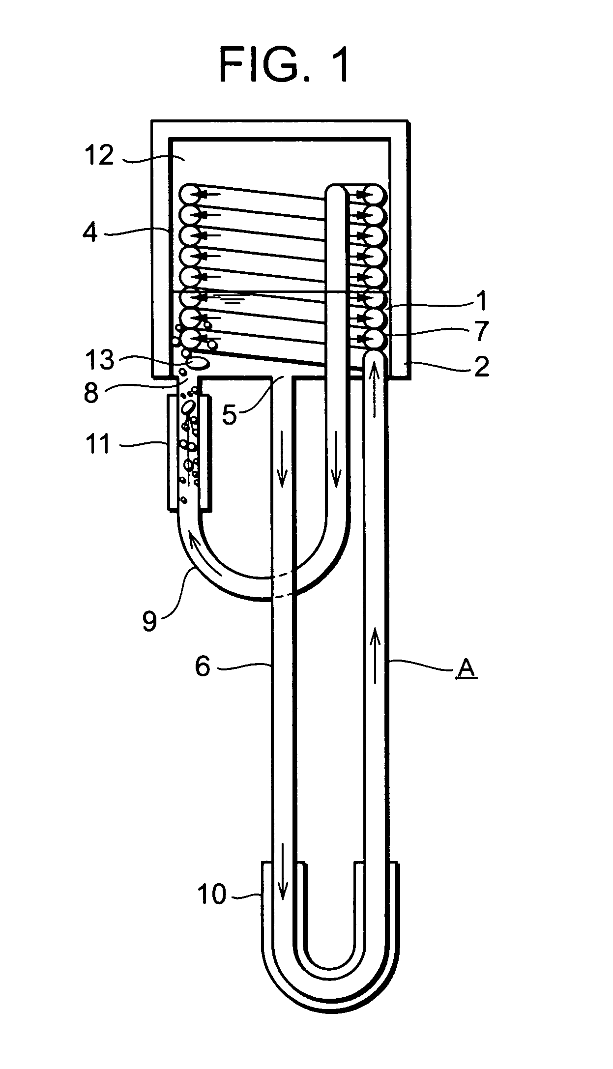
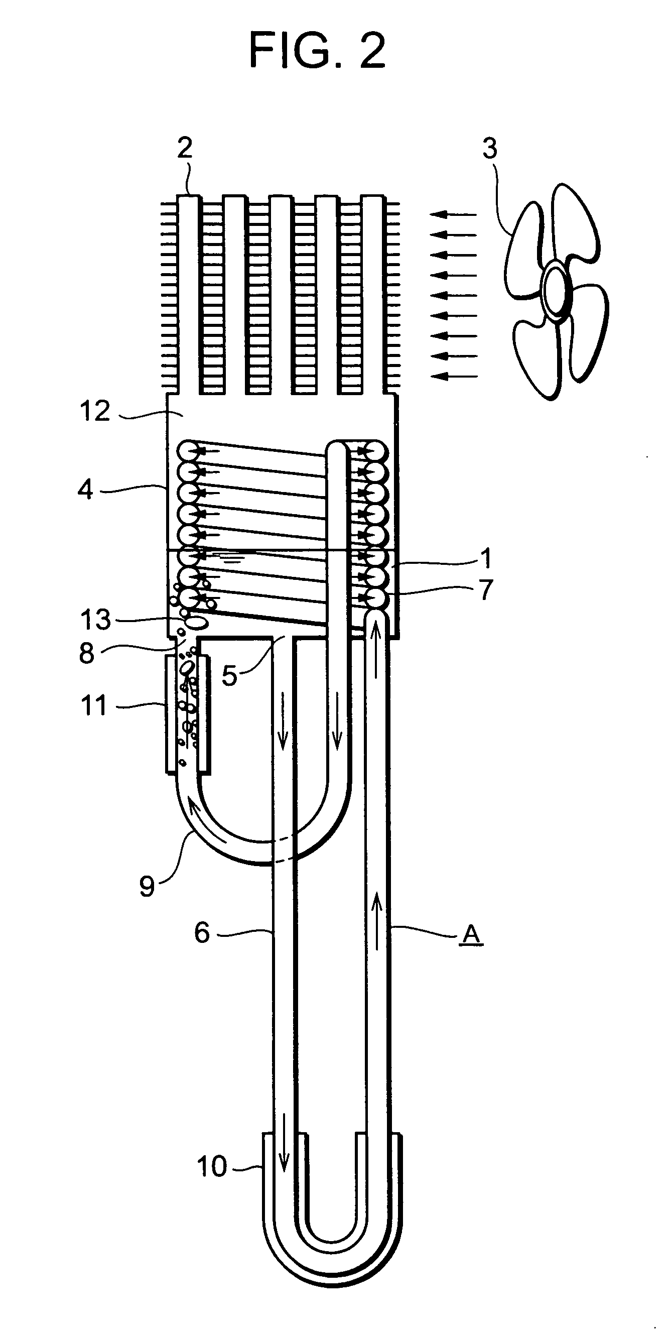
[0030]FIG. 1 is a cross-sectional schematic view illustrating a pump-free water-cooling system according to Embodiment 1 of the present invention. FIG. 2 is a cross-sectional schematic view illustrating another pump-free water-cooling system according to Embodiment 1 of the present invention. In FIG. 1, a heat-exchange circulating solution container 4 contains a high-temperature heat-exchange circulating solution 1 and high-temperature vapor 12 that is produced by phase change of the solution 1 and has latent heat. In addition, a heat radiator 2 is disposed on the outer wall of the heat-exchange circulating solution container 4, whereby the heat of the heat-exchange circulating solution 1 and the vapor 12 is radiated to the heat radiator 2. In this situation, the vapor 12 is condensed into the heat-exchange circulating solution 1 successively. Moreover, in Embodiment 1, the wal...

embodiment 2

[0051]FIG. 4 is a cross-sectional schematic view illustrating a pump-free water-cooling system according to Embodiment 2 of the present invention. In a pump-free water-cooling system according to Embodiment 2 of the present invention, as illustrated in FIG. 4, the heat-exchange circulating solution container 4 is provided with an auxiliary heat-exchange circulating solution container 14 coupled thereto; and a heating device 15 such as a heater is disposed in the auxiliary heat-exchange circulating solution container 14 or on the outer wall thereof.

[0052]The auxiliary heat-exchange circulating solution container 14 may preferably be disposed in a portion other than the gas-liquid two-phase fluid charging pipe between the container 4 and the heating heat exchanger 11, and should merely be disposed in such a way as to communicate with the container 4. In FIG. 4, the auxiliary heat-exchange circulating solution container 14 is communicated with the lower portion of the container 4; howe...

embodiment 3

[0058]FIG. 5 is a cross-sectional schematic view illustrating a pump-free water-cooling system according to Embodiment 3 of the present invention. In the present embodiment, as illustrated in FIG. 5, the heat-exchange circulating solution container 4 is provided with two circulating-solution transporting pipes A. Providing two circulating-solution transporting pipes A increases the heat-transferring area and decreases the thermal resistance. In addition, the heat transportation from scattering high-temperature heat sources, or to scattering low-temperature heat sources is facilitated. Moreover, because the heat-exchange circulating solution container 4 can be shared by a plurality of circulating-solution transporting pipes A, the water-cooling system can be downsized in comparison to that wherein a plurality of heat transportation apparatuses is provided.


PUM


Abstract

A pump-free water-cooling system is provided wherein external power supply is not involved; heat can be transported in any direction; and high reliability and low thermal resistance are ensured.The pump-free water-cooling system includes: a heat-exchange circulating solution container in which a heat-exchange circulating solution and vapor of the circulating solution are contained; a heat radiator provided on the outer wall of the container; a solution outlet for discharging from the container the heat-exchange circulating solution in the container; a gas-liquid two-phase fluid inlet for charging into the container gas-liquid two-phase fluid composed of the heat-exchange circulating solution at high temperature and vapor bubbles of the circulating solution; a first transportation route along which a sensible-heat-emitting heat exchanger is provided, the first transportation route linking with the solution outlet; a second transportation route along which heat exchange is carried out between heat-exchange circulating solution therein and the heat-exchange circulating solution in the container and the vapor of the heat-exchange circulating solution in the container; a third transportation route along which a heating heat exchanger is provided, the third transportation route linking with the gas-liquid two-phase fluid inlet; and a circulating-solution transporting route in which the first transportation route, the second transportation route, and the third transportation route are linked in that order.

Description

BACKGROUND OF THE INVENTION[0001]1. Field of the Invention[0002]The present invention relates to heat transporting apparatus, more particularly to a pump-free water-cooling system that requires no external power supply such as a mechanical pump.[0003]2. Description of the Related Art[0004]In recent years, the calorific values of electronic apparatuses have rapidly been increasing; therefore, higher-efficiency heat radiating means have been required. In addition, the life times of the electronic apparatuses have been prolonged; therefore, higher-reliability heat radiating means have been required. Under this background, heat pipes without moving parts (e.g., refer to Patent Reference 1) have been drawing attention again. Heat pipes are roughly divided into two types, i.e., gravity-type heat pipes (thermosiphon) and capillary-type heat pipes. In a gravity-type heat pipe, an appropriate amount of working fluid is enclosed in an airtight container; and the lower portion of the gravity-t...

Claims


Application Information

Patent Timeline
Patent Type & Authority Patents(United States)
IPC IPC(8): F28D15/00F28D7/04F25D17/00F25D9/00F28D15/02H01L23/473
CPCF28D15/0266H01L2924/0002H01L2924/00
Inventor IPPOUSHI, SHIGETOSHIUEHARA, NOBUAKIYAMADA, AKIRAOGUSHI, TETSURO
Owner MITSUBISHI ELECTRIC CORP
Why Eureka
Try Eureka