Image forming apparatus

a technology of image forming apparatus and forming section, which is applied in the direction of electrographic process apparatus, instruments, optics, etc., can solve the problems of inability to individually replace scanner section or image forming section, inability to flexibly accommodate changes in function, and inability of conventional apparatus to accommodate changes in function

Inactive Publication Date: 2009-03-17
SHARP KK
View PDF9 Cites 0 Cited by
  • Summary
  • Abstract
  • Description
  • Claims
  • Application Information

AI Technical Summary

Benefits of technology

[0010]A feature of the present invention is to provide an image forming apparatus which is capable of easily and effectively utilizing its space section to meet a required function thereby facilitating changes in specifications about processing on recording mediums finished with image formation for improvement in versatility.

Problems solved by technology

For this reason, the post-processing device flanks the image forming apparatus to enlarge the footprint of the apparatus as a whole, with the result that the image forming apparatus requires an increased space for its installation.
Because the conventional image forming apparatus, as a whole, has an integral configuration comprising the scanner section and the image forming section, the scanner section or the image forming section cannot individually be replaced with an alternative.
For this reason, the conventional apparatus cannot flexibly accommodate changes in function such as processing speed changes or replacements required in the event of failure.
Though the arrangement described in the former publication utilizes the space formed between the scanner section and the image forming section, the delivered sheet tray and the post-processing device are fixedly disposed in the space and, hence, the space cannot be utilized more effectively.
The arrangement described in the latter publication is characterized by comprising replaceable modules or units for replacement when necessary for improvement in the performance of the apparatus, but is not designed to utilize such a space effectively.

Method used


Image

  • Image forming apparatus
  • Image forming apparatus
  • Image forming apparatus

Examples


Embodiment Construction

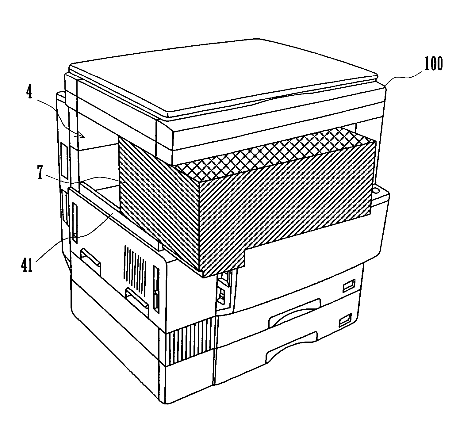
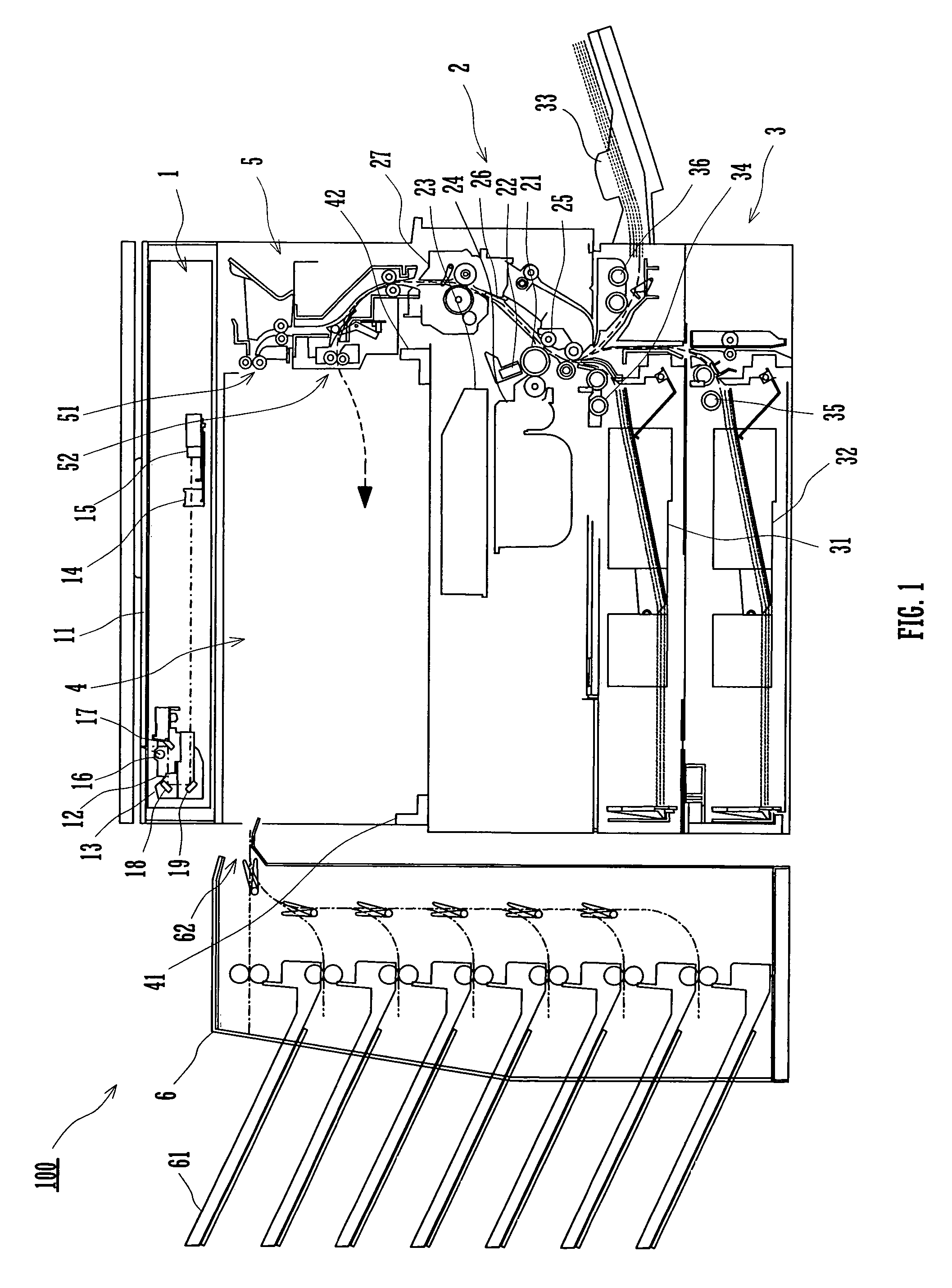
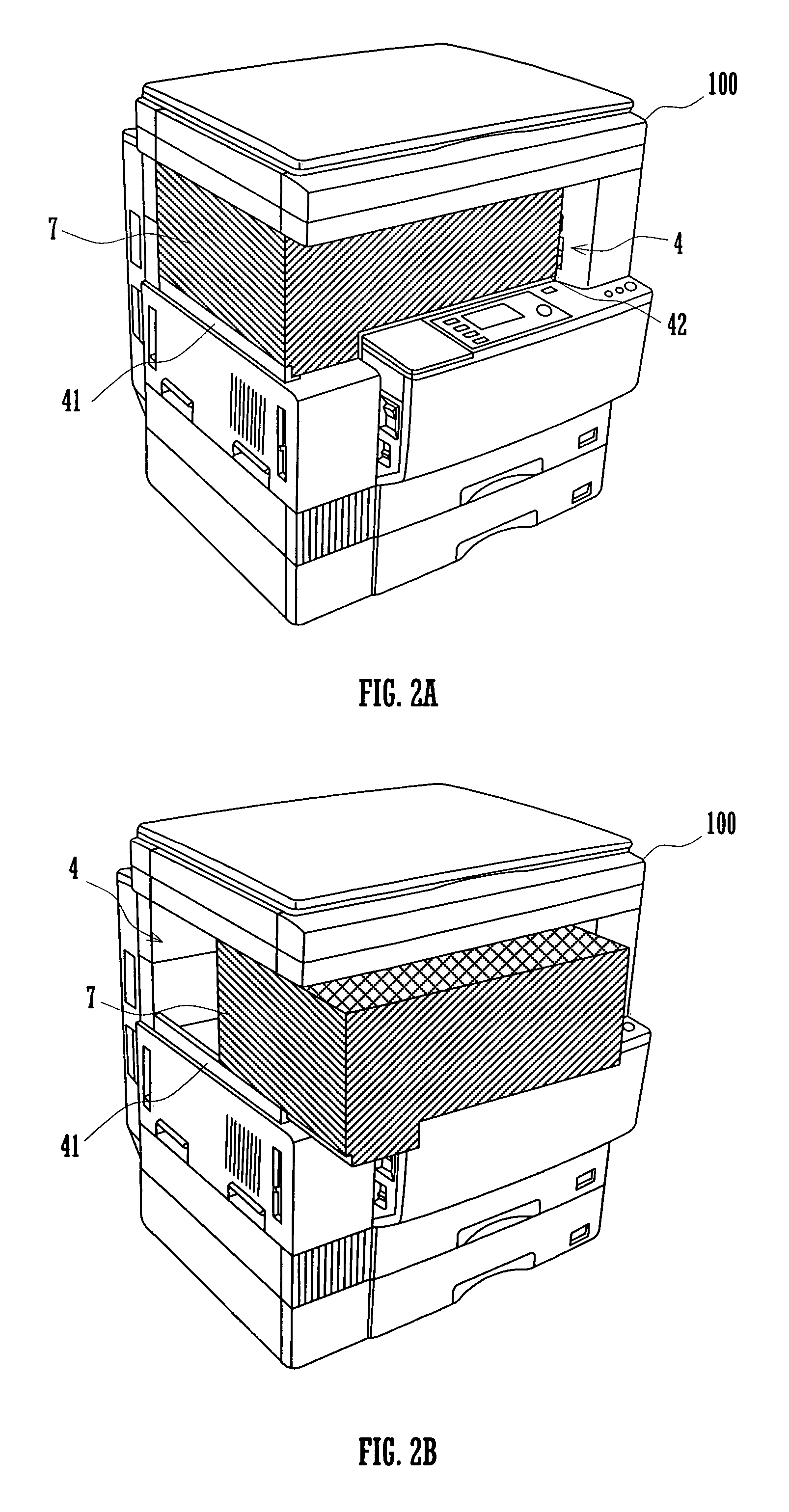
[0023]Hereinafter, the construction of an image forming apparatus according to the present invention will be described in detail with reference to the accompanying drawings. FIG. 1 is a schematic view showing the construction of an image forming apparatus according to an embodiment of the present invention. The image forming apparatus 100 shown includes a scanner section 1, an image forming section 2, a sheet feed section 3, a space section 4, a delivery section 5, and a post-processing device 6.

[0024]The image forming section 2 is disposed below the scanner section 1, with the space section 4 and delivery section 5 intervening therebetween. The sheet feed section 3 is located below the image forming section 2. The post-processing device 6, which corresponds to the post-processing section defined by the present invention, is fitted on the left-hand side of the image forming apparatus 100.

[0025]The scanner section 1 includes a platen 11 on the upper side thereof, and, below the plate...


PUM


Abstract

An image forming apparatus includes a scanner section, an image forming section, and a functional unit. The scanner section is configured to read image information by scanning an image bearing side of a document sheet. The image forming section is located above or below the scanner section with a space section provided therebetween and is configured to perform image formation processing on a recording medium based on the image information read. The space section has at least one open vertical side. The functional unit is removably fitted into the space section through the open side.

Description

CROSS REFERENCE[0001]This Nonprovisional application claims priority under 35 U.S.C. § 119(a) on Patent Application No. 2004-368428 filed in Japan on Dec. 20, 2004, the entire contents of which are hereby incorporated by reference.BACKGROUND OF THE INVENTION[0002]The present invention relates to an image forming apparatus configured to perform image formation processing on a recording medium by an image forming section based on image information read from a document at a scanner section.[0003]Among conventional image forming apparatus, such as copying machines and multifunctional digital processors, of the type having a scanner section for reading image information from an image bearing side of a document sheet and an image forming section for performing image formation processing based on such image information, there is one which is provided with a post-processing device for performing post-processing on a recording medium finished with image formation. Examples of such post-proce...

Claims


Application Information

Patent Timeline
Patent Type & Authority Patents(United States)
IPC IPC(8): G03G15/00
CPCG03G15/6552G03G21/1609G03G2221/16G03G2221/1678G03G2221/1696B65H2402/10
Inventor YOSHIDA, KENZOKANAOKA, YUKIOFUKUNAGA, TAKAHIRONAGATA, JINICHIYOSHIKAWA, HIDEOMATSUDA, TAKASHI
Owner SHARP KK
Why Eureka
Try Eureka