Subsea pressure accumulator systems

a technology of accumulator and submerged water, which is applied in the direction of fluid coupling, sealing/packing, and wellbore/well accessories, etc., can solve the problems of rendering the accumulator non-functional, and achieve the effect of effective boosting the force, boosting the pressure, and reducing the number of containers or bottles for compressed gas

Active Publication Date: 2009-04-21
VARCO I P INC
View PDF28 Cites 64 Cited by
  • Summary
  • Abstract
  • Description
  • Claims
  • Application Information

AI Technical Summary

Benefits of technology

[0014]The present invention, in certain aspects, discloses a pressure compensation system for subsea apparatus which has one or more hydraulic power units used in an hydraulic fluid system. In certain aspects, such subsea apparatus employs one or more hydraulic fluid reservoirs and / or accumulators which releasably hold operational amounts of hydraulic fluid at a pressure slightly greater than the pressure of water exterior to the reservoir for selectively operating subsea equipment and systems, e.g. BOP's, coiled tubing units, valves, and subsea wellhead connectors. The reservoir and / or accumulator(s) can require a substantial amount (e.g. 50, 100, 500 gallons or more) of hydraulic fluid which can entail the flow of this substantial amount of fluid from a reservoir to the accumulator(s). In certain systems according to the present invention, a “seawater boost” is provided which includes exposing a piston end to the pressure of the seawater. This piston effectively boosts the force provided by another piston which is acted upon by compressed gas to move a power fluid out of the system. By using the seawater boost effect, the required number of containers or bottles for compressed gas is reduced. The seawater boost can boost the pressure on contained hydraulic fluid in addition to the pressure of gas on the fluid, thus reducing the amount of pressurized gas required to achieve a certain pressure on the hydraulic fluid.
[0015]In certain aspects, the reservoir is initially charged at a pressure slightly higher than the pressure of the water to be encountered at depth and the reservoir is pressure compensated so that at depth it is not damaged or destroyed.
[0020]Such systems which can effectively provide significantly large volumes of power fluid.

Problems solved by technology

Any fluid introduced for storage causes the pressure to exceed the working pressure, rendering the accumulator non-functional.

Method used


Image

  • Subsea pressure accumulator systems
  • Subsea pressure accumulator systems
  • Subsea pressure accumulator systems

Examples


Embodiment Construction

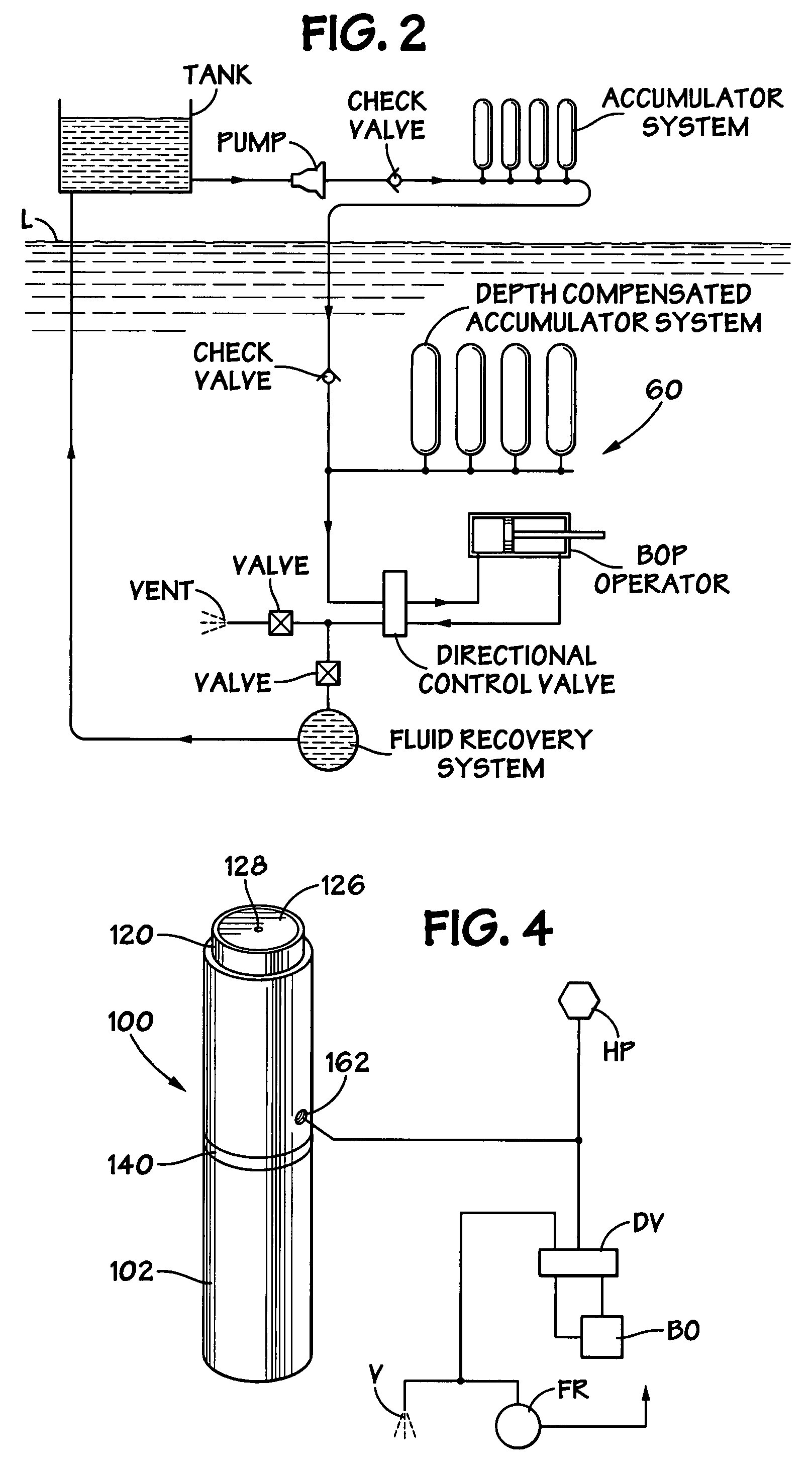
[0046]FIG. 2 shows a system 60 according to the present invention in which power fluid from an hydraulic power unit is provided to a subsea blowout preventer operator (“BOP OPERATOR”). Hydraulic power fluid is pumped from a reservoir (“TANK”) by a pump (“PUMP”) through a check valve (“CHECK VALVE”) to a bank of accumulator containers at the surface (“ACCUMULATOR SYSTEM”). This fluid is then provided beneath a water level L through a check valve (“CHECK VALVE”) to an accumulator system according to the present invention with one or more depth compensated containers or bottles according to the present invention (“DEPTH COMPENSATED ACCUMULATOR SYSTEM”). A control valve (“DIRECTIONAL CONTROL VALVE”) selectively provides the power fluid from the depth compensated accumulator containers to operate a subsea device or apparatus, e.g. the BOP operator shown. Fluid exhausted from the BOP operator either flows into the water (“VENT”) or to a fluid recovery system (“FLUID RECOVERY SYSTEM”) from...


PUM


Abstract

An accumulator system which, in certain aspects, has a body with three (or more) interior chambers, e.g. in one aspect first, second, and third chambers, the body having a first body end with a first opening, and a second body end with a second opening, an amount of operational power fluid in the first chamber, an amount of pressurized gas in the second chamber for moving a piston assembly for moving power fluid from the body to operate an apparatus, the piston assembly having a cavity within a piston end for containing additional pressurized gas for moving the piston assembly.

Description

BACKGROUND OF THE INVENTION[0001]1. Field of the Invention[0002]The present invention is directed to underwater accumulator systems which provide pressurized working fluid.[0003]2. Description of Related Art[0004]Deepwater accumulators provide pressurized working fluid for the control and operation of equipment, e.g. for blowout preventer operators; gate valves for the control of flow of oil or gas to the surface or to other subsea locations; hydraulically actuated connectors; and similar devices. The fluid to be pressurized is typically an oil based product or a water based product with added lubricity and corrosion protection, e.g., but not limited to hydraulic fluid.[0005]Certain prior art accumulators are precharged with pressurized gas to a pressure at or slightly below an anticipated minimum pressure required to operate equipment. Fluid can be added to the accumulator, increasing the pressure of the pressurized gas and the fluid. The fluid introduced into the accumulator is st...

Claims


Application Information

Patent Timeline
Patent Type & Authority Patents(United States)
IPC IPC(8): F16D31/02
CPCE21B33/0355E21B34/04F15B1/24F15B2201/205F15B2201/31F15B2201/41F15B2201/4155
Inventor SPRINGETT, FRANK B.
Owner VARCO I P INC
Why Eureka
Try Eureka