
Lock with indicator and multiple key-actuated core
a technology of indicator and core, which is applied in the field of locks, can solve the problems of inability of the lock structure to indicate whether the core is present, disadvantages of the lock structure mentioned in the above patents, and the inability of the lock structure to indicate whether
- Summary
- Abstract
- Description
- Claims
- Application Information
AI Technical Summary
Benefits of technology
Problems solved by technology
Method used
Image

Examples
Embodiment Construction
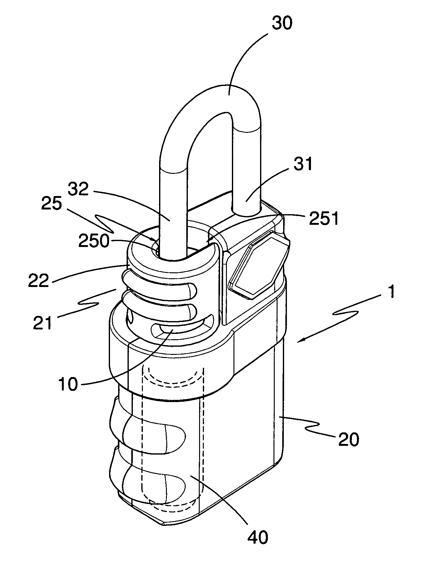
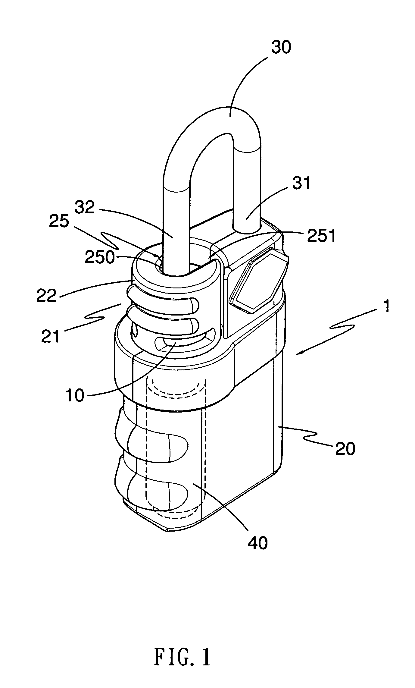
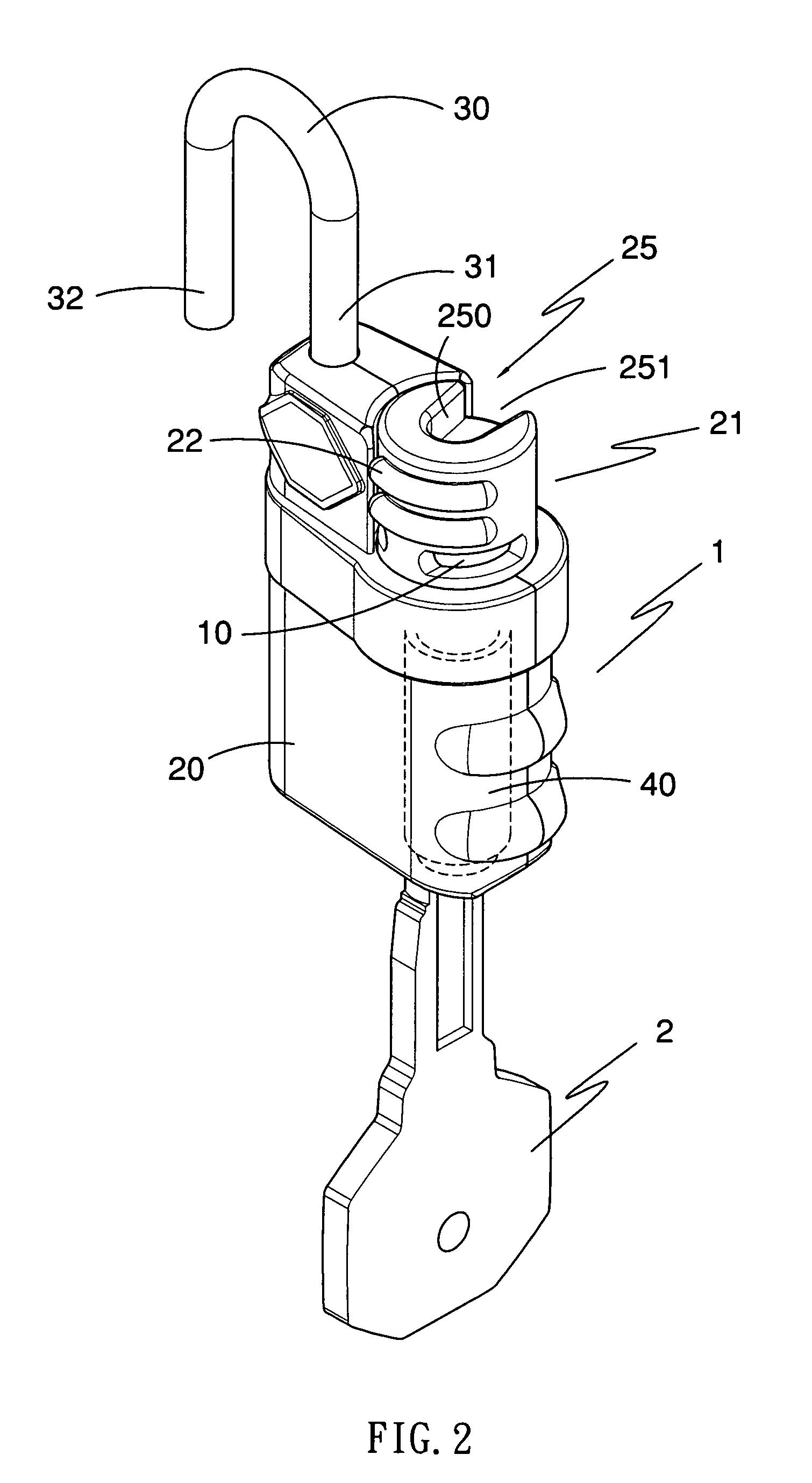
[0027]With reference to FIG. 1, it is noted that the lock structure 1 in accordance with the present invention includes a casing 20, a latch retaining member 21, a core 40 rotatably received in the casing 20, an indicator 10 movably received in the casing 20, the latch retaining member 21 including a latch seat 22 firmly connected to the core 40 to simultaneously rotate with the core 40 and rotatably mounted on top of the casing 20 and a latch 30 one end of which is securely received in the casing 20 and the other end of which is alternately received in the latch seat 22.
[0028]With reference to FIGS. 2 and 3, it is to be noted that the core 40 of the present invention is adapted for a private key 2 and a general key 3. That is, both the private key 2 and the general key 3 are able to activate the core 40 to drive the latch seat 22 to rotate so as to release a limitation to a free end of the latch 30.
[0029]With reference to FIGS. 4-6, it is noted that the indicator 10 is composed of ...
PUM
 Abstract
Description
Claims
Application Information