Low profile receptacle connector straddle-mounted on the PCB

a low-profile, connector technology, applied in the direction of coupling device connection, electrical apparatus, coupling protective earth/shielding arrangement, etc., can solve the problem that the shield case is adverse to the minimization of the connector by the hole mounting

Inactive Publication Date: 2009-06-23
HON HAI PRECISION IND CO LTD
View PDF8 Cites 54 Cited by
  • Summary
  • Abstract
  • Description
  • Claims
  • Application Information

AI Technical Summary

Benefits of technology

[0007]Accordingly, an aspect of the present invention is to provide a reliable receptacle connector. The present invention referring to a receptacle connector comprise: a dielectric housing forming recesses therein, a plurality of terminals receiving in the recesses, and a metal shield enclosing the dielectric housing. The metal shield contains the cover and the base. A pair of fingers extending from the cover and a pair of arms extending from the base hold the rear end of the housing. The arms and the fingers are in pairs and arranged in symmetrical making the dielectric housing in perfect balance.
[0008]Another aspect of the present invention is to provide a receptacle connector whose metal shield is easy to manufacture. The metal shield contains the cover and an opposite base. The cover has a top wall and a pair of top lateral walls standing at bilateral of the top wall. There are top bottom wings extending from the end of the lateral walls. The base contains a bottom wall and a pair of curve portions adjoining the bottom wall, and a pair of bottom lateral wings extending from the end of the curve portions. Either the main body of the cover or the base, can be shaped in one press processing, this processing increase the productivity of the metal shield and make the assembling of the receptacle connector more convenient.

Problems solved by technology

The through-hole mounting of the shield case is adverse to the minimization of the connector.

Method used


Image

  • Low profile receptacle connector straddle-mounted on the PCB
  • Low profile receptacle connector straddle-mounted on the PCB
  • Low profile receptacle connector straddle-mounted on the PCB

Examples


Embodiment Construction

[0013]Reference will now be made to the drawings to describe the present invention in detail.

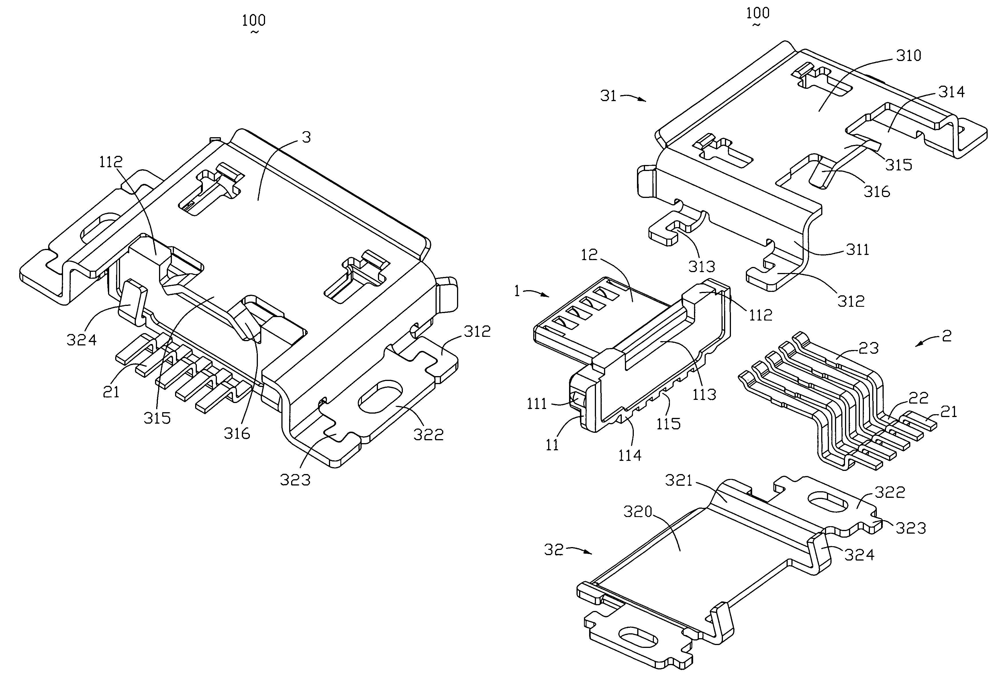
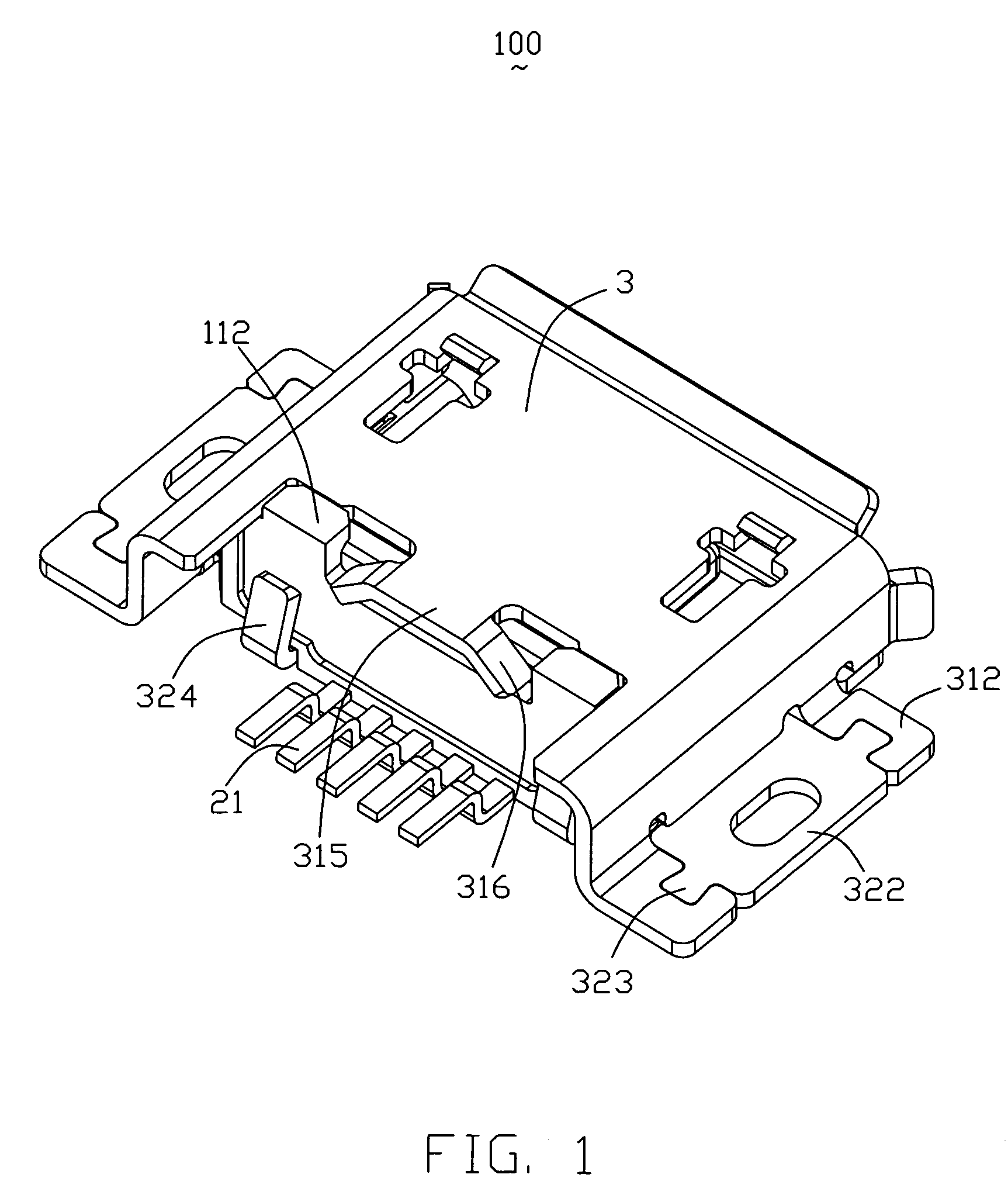
[0014]Referring to FIG. 1, depicts an embodiment of a receptacle connector 100, the connector can be installed on a substrate for example a print circuit board (PCB), and the like.

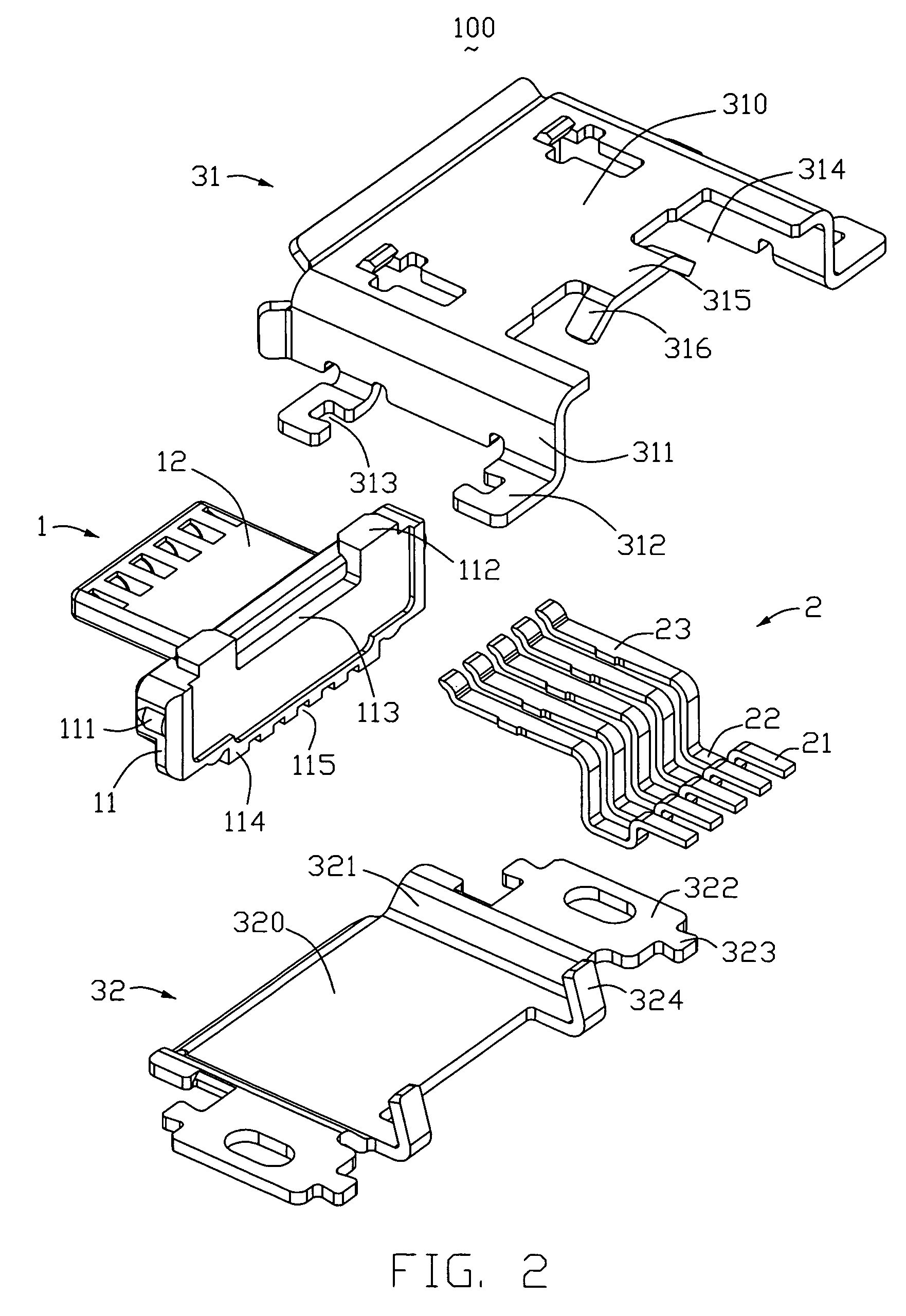
[0015]A receptacle connector 100 includes: a dielectric housing 1 forming recesses 115 / 121 therein, a plurality of terminals 2 received in the recesses 114 / 121, and a metal shield 3 enclosing the dielectric housing 1.

[0016]Elements of receptacle connector 100 are shown clearly in FIG. 2 and FIG. 3. The dielectric housing 1 contains a base portion 11 and a tongue portion 12 extending from the base portion 11. The base portion 11 assumes rectangular parallelepiped, the left and right lateral face of the base portion 11 form a pair of cylinder cams 111, two blocks 112 project from the top face of the base portion 11, a corner 113 is located between the blocks 112 defining a slot, a pair of curbs 114 is shaped near bot...


PUM


Abstract

A receptacle connector (100) includes a metal shield (3) having the cover (31) and an opposite base (32). The cover (31) includes a pair of top lateral wings (312). The base includes a pair of bottom lateral wings (322) for mating with the respective top lateral wings (312). The top lateral wing (312) defines a first portion of a whole lateral wing board, while the bottom lateral wing (322) defines a second portion adapted to contribute towards completing the whole lateral wing board. Thus, the metal shield (3) is integrated by the cover (31) and the base (32), each of which is molded by a single sheet.

Description

BACKGROUND OF THE INVENTION[0001]1. Field of the Invention[0002]The present invention relates to an electrical connector, and more particularly to a low profile receptacle connector straddle-mounded into a cutout of a substrate. The connector includes a metal shell featured with supporting tabs securely disposed onto the substrate.[0003]2. Description of the Prior Art[0004]U.S. Pat. No. 7,252,549 issued to Mitsumi Electric Co., Ltd., on Aug. 7, 2007 discloses 'A connector includes a receptacle 1 to be mounted on a substrate 11 and a plug 5 adapted to be connected to the receptacle 1. The receptacle 1 has a shield case 2 provided with connection terminals 31 therein, and the plug 5 has a shield case 6 provided with connection terminals 71 therein. The shield case 6 of the plug 5 is adapted to be inserted into the shield case 2 of the receptacle 1 when the plug 5 is connected to the receptacle 1, at which the connection terminals 71 of the plug 5 are electrically connected to the conn...

Claims


Application Information

Patent Timeline
Patent Type & Authority Patents(United States)
IPC IPC(8): H01R13/648
CPCH01R12/716H01R13/6581H01R12/707H01R12/57H01R13/504
Inventor ZHANG, HAN-MINGWATANABE, TSUNEKIXIAO, JIAN-PING
Owner HON HAI PRECISION IND CO LTD
Why Eureka
Try Eureka