Keyed handgrip assembly

a keyed and handgrip technology, applied in the field of keyed handgrip assembly, can solve the problems of none of the above being removable with any degree of convenien

Active Publication Date: 2009-12-01
LIFELINE INT +2
View PDF11 Cites 19 Cited by
  • Summary
  • Abstract
  • Description
  • Claims
  • Application Information

AI Technical Summary

Benefits of technology

[0026]The cross-sectional dimensions of the intermediate shank (712) are also important to provide proper snap-fit installation into the axial conduit (201) as well as to assure reliable retention therein (201), once so positioned.

Problems solved by technology

None of those were removable with any degree of convenience, however, a screwdriver was required to pry loose the core (902) of the snap-in-place Hinds model.

Method used


Image

  • Keyed handgrip assembly
  • Keyed handgrip assembly
  • Keyed handgrip assembly

Examples


Embodiment Construction

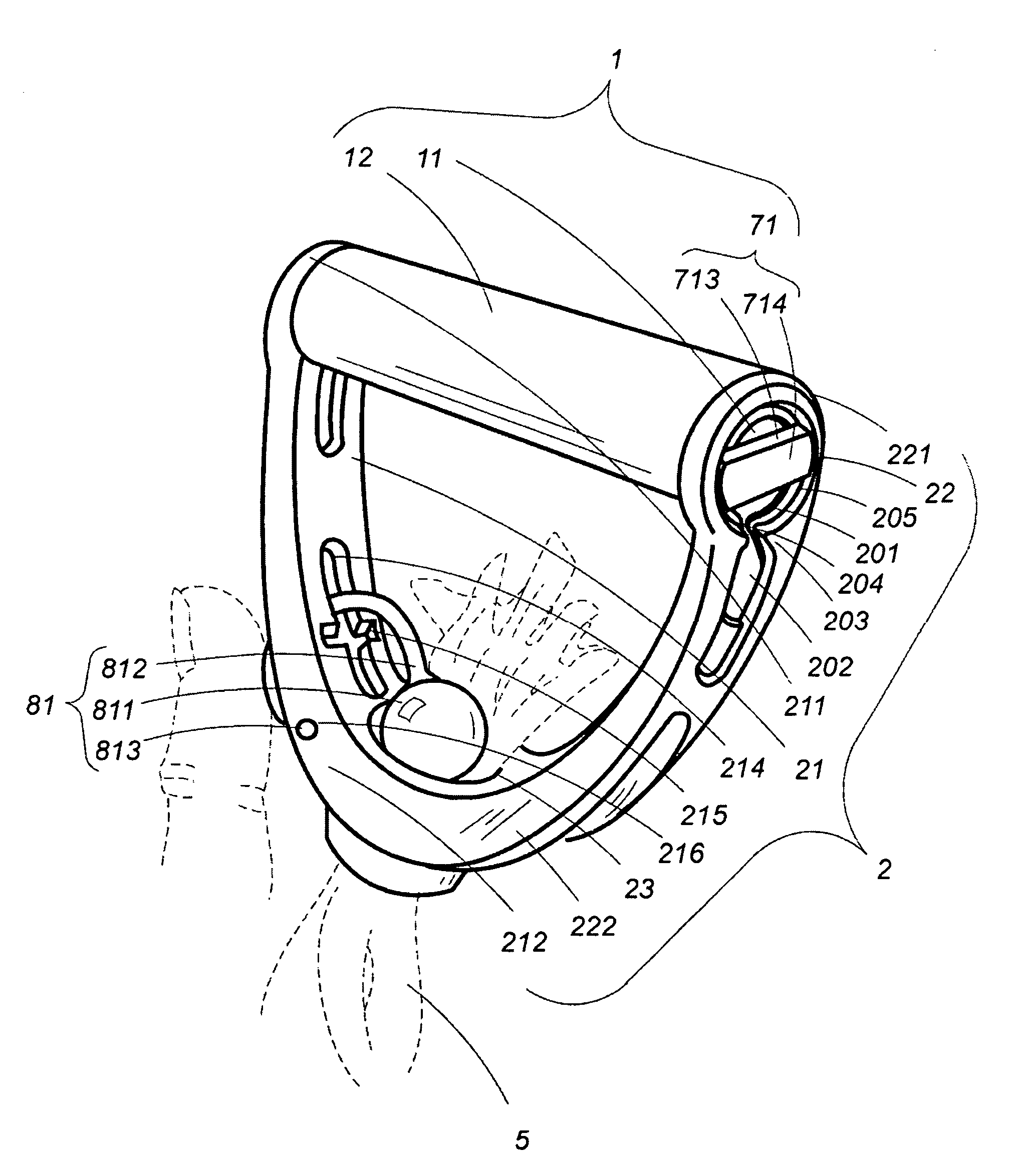
[0037]The subject matter hereof comprises a special exercise handgrip comprising in combination two interconnecting parts—the first, a handgrip frame (2)—the usually “U”-shaped part of a solid or stirrup handgrip; the second, a keyed handhold (1).

[0038]The handgrip frame (2) comprises in part first and second opposing extending prongs (21, 22, respectively).

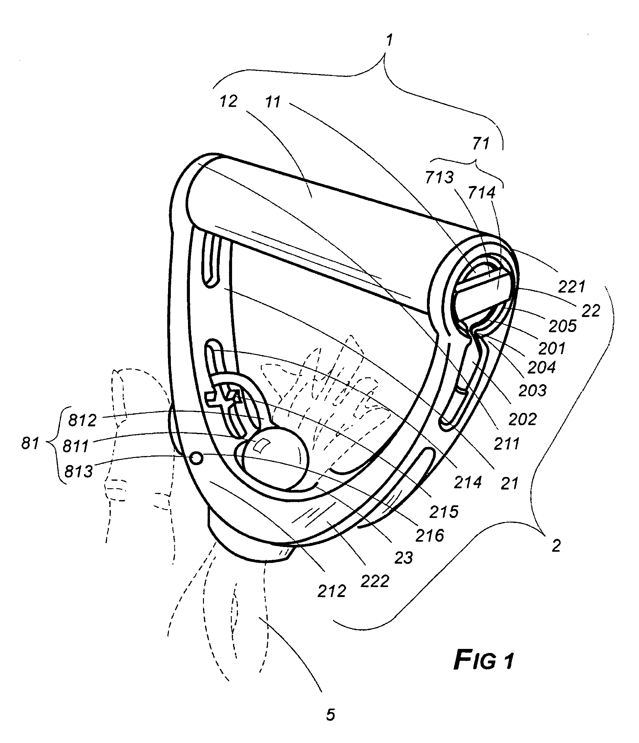
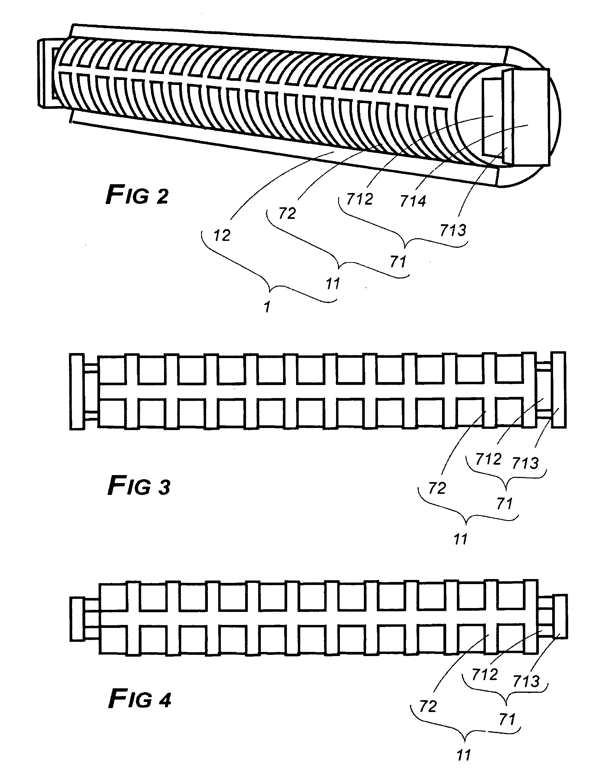
[0039]The keyed handhold (1) comprises a generally elongated handhold core (11) in turn comprising paired axial key stop pedestals (71) which are oppositely disposed—that is, one at each end thereof (11). Each pedestal (71) is configured to comprise an intermediate shank (712) disposed at the innermost end thereof (712) in what is herein designated axial attachment to and extension from an end of the core (11). Each pedestal (71) further comprises transversely disposed upon the outermost end of its intermediate shank (712) a flange (713) in turn comprising an outwardly disposed face (714).

[0040]The prongs (21, 22) of the handgrip...


PUM


Abstract

The handhold of an exercise handgrip turns freely while seated between the open ends of the upwardly extending prongs. It can be easily removed by moving the specially formed end part of the handhold into an access opening wide enough to slip the end part through. In positioning the handhold's end part for this removal, it must be forcibly snapped through a narrow opening. By reversing the procedure, the handhold can easily be returned to its place of rotation. The specially formed end part of the handhold must, therefore, have a narrow neck-like portion to fit through the narrow opening but the end part must also be enlarged to keep it in place for rotation. Preferably, there is also a stem and ball unit in one of the prongs which swings into place to trap exercise sheeting, cord or other media within an opening at the handgrip's bottom portion.

Description

CROSS-REFERENCE TO RELATED APPLICATIONS[0001]This instrument, filed under 37 CFR 1.53(b) and 1.78 invoking the provisions of 35 U.S.C. 120, is a Continuation in Part of currently abandoned application Ser. No. 11 / 544,357 entitled “Retained Impinger for Universal Sports Use”, filed Oct. 6, 2006.STATEMENT REGARDING FEDERALLY SPONSORED RESEARCH OR DEVELOPMENT[0002]Not ApplicableTHE NAMES OF THE PARTIES TO A JOINT RESEARCH AGREEMENT[0003]Not ApplicableINCORPORATION-BY-REFERENCE OF MATERIAL SUBMITTED ON A COMPACT DISC[0004]Not ApplicableBACKGROUND OF THE INVENTION[0005]1. Field of the Invention[0006]Exercise equipment[0007]2. Description of Related Art[0008]Occasionally a descriptive term in this application may be shortened so as to recite only a part rather than the entirety thereof as a matter of convenience or to avoid needless redundancy. In instances in which that is done, applicant intends that the same meaning be afforded each manner of expression. Thus, the term impediment passa...

Claims


Application Information

Patent Timeline
Patent Type & Authority Patents(United States)
IPC IPC(8): A63B21/02
CPCA63B21/1469A63B21/1434A63B21/0552A63B21/4035A63B21/4017
Inventor HINDS, ROBERT SYLVESTERBONNEVILLE, LOYD WILLIAM
Owner LIFELINE INT
Why Eureka
Try Eureka